
Instruction manual

MERLIN LEGEND Communications System Release 5.0
System Planning
555-650-112
Issue 1
June 1997
Unit Load Calculation
Page F-8
F
Continued from previous page
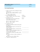
† The MFM has its own wall power unit located at the telephone and, therefore, is not added to
the unit load calculation.
‡ Up to two DSSs (one DSS for each MLX-28D or MLX-20L) can be powered from each control
unit carrier. For example, a three-carrier system can have six system operator positions, each
with one DSS powered from the control unit.
9. Try to exchange modules between carriers to reduce the unit loads for slots
5 and 6 through 27. (Remember that the 100D, 800 NI-BRI, 400, 400
GS/LS, 800, and 800 GS/LS modules have unit loads of 0.0.) Repeat Steps
1 through 8 to recalculate unit loads for each new configuration.
NOTES:
Empty slots are not permitted between modules.
■
If the unit load for slots 5 and 6 is less than or equal to 27, power is suf-
ficient for the carrier.
■
If the exchange does not reduce the unit load for slots 5 and 6 to 27, in-
stall wall power units for the appropriate number of telephones to reduce
the unit load to 27.
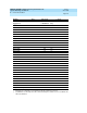
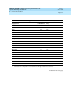
Module Qty x Unit Load = Total
Equipment
Hybrid/PBX
or Modified
Key
MDC 9000 0.0 0.0
MDW 9000 0.0 0.0
10-Button Basic 0.9 1.1
Optional Equipment
†
10-Button HFAI 1.0 1.2
34-Button Basic 0.9 1.1
34-Button DLX 1.2 1.7
34-Button BIS 1.2 1.4
34-Button BIS/DIS 1.2 1.4
Single-Line Telephone 0.6 0.7
Direct Station Selector
‡
0.7 0.9
General-Purpose Adapter 0.8 1.0
Hands-Free Unit 0.8 1.0
Headset Adapter 0.8 1.0
Total Actual Unit Load