
Installation manual


! " #$%$ & ' #
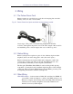
=<+ . ! " - ( > <% " " 3 * 6 ( > <4 .
8
7
6
5
4
3
2
1
8
7
6
5
4
3
2
1
1 2 3 4 5
6 7 8 9
1 2 3 4 5
6 7 8 9
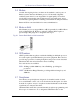
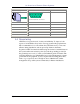
view from back side of connector.
Pin 1 Pin 9 22
Pin 2 Pins 1, 6, 8 6 + 8
Pin 3 Pin 4 20
Pin 4 Pin 5 7
Pin 5 Pin 2 3
Pin 6 Pin 3 2
5 7 . ,
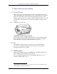
AT&T has a long track record of safety and reliability. To improve both
aspects of an installation, they insist on strong ground wiring requirements.
My recommendation is to follow them; they take little money, a few extra
minutes during installation, and can prevent problems in the future.
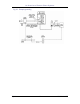
In general, AT&T recommends additional ground wires be installed between
the system and known reference points (beyond the grounding provided in
the grounded power cord.). Consult your installation guides for details. The
following illustration, for a Merlin Plus, has a typical arrangement: separate
ground wire from equipment, closely coupled to the incoming phone lines,
back to a good ground source. Though we show a Merlin here, similar
arrangements are possible (and recommended) for Partner installations.