
Installation manual


! " #$%$ & '
; / / - ' ( * % * . +
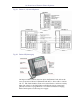
The MDC 9000 was designed for use with Partner, Merlin, and Definity
systems, so is not optimized for Partner, but claims to be fully compatible. It
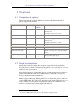
provides 6 line/feature buttons with a status display for the buttons.
Like the MLC-6, the MDC 9000 used a standard handset plus base
arrangement. Using newer technology (the “D” in MDC stands for “Digital”),
this set provided digital transmission for greater range, clarity, and security.
The base station can be wall or desk mounted. A standard “wall-wart” power
supply provides necessary DC to the base. A headset jack allows an optional
headset to be connected.
This set used the 902-927 MHz radio band, with 50 total channels
dynamically allocated out of 173 available channels.
, 4 ' ( * % * . .
= / / - ' ( 1 % * . +
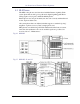
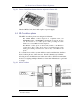
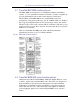
AT&T introduced the TransTalk MDW “Multi-line Digital Wireless” series
in 1995 to replace and extend the MDC series. This series was designed for
larger installations, and separates the charging base from the transmitter.
Transmitters are installed in carriers (backplanes), supporting 2-6 phones
used in the same area. Use of the carrier keeps radio signals coordinated,
promoting higher quality service when multiple MDWs are in operation
nearby.