
Cordless Telephone User Manual


Preparation
Prepare the IPC-1600 for Installation
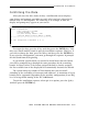
Set the Controller Memory Starting Address
Locate the DS1 Dual In-line Package (DIP) switch (a group of eleven
switches) on the IPC-1600. Refer to Appendix A, “Hardware Parameter
Settings,“ for switch location information and instructions on how to set the
controller memory starting address (DS1, SW8 through SW1) to correspond to
the values established when installing the software (Chapters 2 and 3).
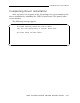
Set the Input/Output Port Address
Next, locate the DS1 DIP switch. Set the selected I/O port address (DS1,
SW11 through SW9). For switch location information and instructions on how
to set the selected I/O starting address, refer to Appendix A. Set the I/O port
address switches to correspond with the values specified when installing the
software (Chapter 2 and 3).
If you are adding more than one board, make sure that the selected I/O
starting addresses you are now specifying do not conflict.
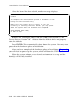
Set the Interrupt Request Level
Locate the DS2 DIP switch. Follow the instructions in Appendix A for
setting the IRQ level. Again, each IPC-1600 board that you install can have
its own IRQ level or one IRQ can be used for all IPC-1600 boards. Set the
IRQ switches to correspond to the IRQ level specified when installing the
software (Chapters 2 and 3).
HARDWARE INSTALLATION 4-3