
System information


DCS Administration
4-2 Issue 1 October 1997
Data Link Administration
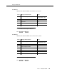
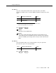
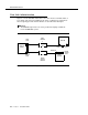
Figure 4-1 shows that DCS switch data connections involves a distant switch, a
host switch, and an I
NTUITY AUDIX system. Some coordination is required here
when assigning port and channel numbers as described after this figure.
NOTE:
The GBCS Design Center can assist you when designing a multinode
I
NTUITY AUDIX DCS system.
Figure 4-1. INTUITY AUDIX System Data Link to a DCS Switch
1
1
Node #1
(Host)
DCS
Channel
INTUITY
System
Channel
Node #2
64
2
64
2
2
4
3 59
INTUITY
System
1
2
INTUITY
System
Link
Host
Link
DCS Remote
Link
Data Link
INTUITY
System
Port
Switch
Port