
System information


Switch Integration Requirements
1-4 Issue 1 October 1997
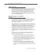
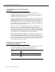
Figure 1-1. System 85 or G2 with a Single Common Control IDI
Connection to the Lucent INTUITY System
Using a Duplicated Common Control
Use the following IDI connection for a Lucent INTUITY system and a System 85/G2
switch with a duplicated common control. Figure 1-1 shows the connections for
the System 85 and DEFINITY G2 switches.
The IDI uses a Electronic Industries Association (EIA) RS-232-C serial data
electrical interface. Therefore, a Lucent I
NTUITY system platform and a switch
connected through an IDI cannot be over 50 ft apart.
Hardware Required for the Connection
■ One IDI
■ One ED-1E434-11, Group 175 cable (RS-232C to RS-449 transition cable,
3.0 ft) and a 25-pin male connector at the RS-232 connection on the face-
plate of the MAP computer.
■ One ED-1E434-11, Group 304 cable (RS-449 male), the length of which
may not exceed 50 ft (Attribute LNG11).
■ One ED-1E434-11, Group 342 cable (RS-449 male).
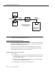
GPSync
Board
MAP/40
ED1E43411-
Grp 175
RS-232 to
RS-449
IDI
OUT
System 85 or
DEFINITY G2
GPSync
Board
MAP/100
25-pin male
connector
IN
DCIU
J2
J1
ED1E43411-
Grp 304
RS-449
Total distance from switch
to Lucent I
NTUITY system
not to exceed 50 ft.