
System information


GPSC/AT/E
Issue 1 October 1997
1-3
GPSC/AT/E
For all integrations of the subject switches with the Lucent INTUITY system, a
general-purpose synchronous controller AT-enhanced (GPSC/AT/E) card is
required. The GPSC card communicates with the switch through the DCIU link
and transfers digital call information.
LUCENT INTUITY System Switch
Connections
Use the information and diagrams in this section to understand the different
configurations for connecting a Lucent I
NTUITY system with a System 85 and
DEFINITY G2 switch. You can only use the Isolating Data Interface (IDI) to
connect the Lucent I
NTUITY system to the switch, in one of the following
configurations:
■ Using a single common control
■ Using a duplicated common control
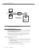
Using a Single Common Control
Use the following IDI connection for the Lucent INTUITY system and the System
85/G2 switch with a single common control. Figure 1-1 shows you the
connections for the System 85 and DEFINITY G2. Study the diagram to
understand the connections.
The GPSync card uses an Electronic Industries Association (EIA) RS-449 serial
data electrical interface. Therefore, a Lucent I
NTUITY system platform and a
switch connected through an IDI cannot be over 50 ft apart.
Hardware Required for the Connection
■ One IDI, which is used for electrical protection
■ One ED-1E434-11, Group 175 cable (RS-232C to RS-449 transition cable,
3.0 ft) and a 25-pin male connector at the RS-232 connection on the face-
plate of the Multi-Application Platform (MAP) computer
■ One ED-1E434-11, Group 304 cable (RS-449 male), the length of which
may not exceed 50 ft (Attribute LNG11)