INTUITY™ Integration with System 85 and DEFINITY® Communications System Generic 2 585-310-256 Comcode 108099615 Issue 1 October 1997
Copyright 1997, Lucent Technologies All Rights Reserved Printed in U.S.A. Notice Every effort was made to ensure that the information in this book was complete and accurate at the time of printing. However, information is subject to change. Your Responsibility for Your System’s Security Toll fraud is the unauthorized use of your telecommunications system by an unauthorized party, for example, persons other than your company’s employees, agents, subcontractors, or persons working on your company’s behalf.
Contents About This Book ■ ■ ■ ■ ■ ■ ■ xi Purpose Intended Audiences Release History Conventions Used in This Book Terminology Keyboard and Telephone Keypad Representations Screen Displays Data Entry Conventions Safety and Security Alert Labels Trademarks and Service Marks Related Resources Documentation Training Technical Assistance How to Comment on This Book xi xi xi xi xii xiv xv xv xvi xvi xviii xviii xviii xviii xix System Security and Toll Fraud ■ ■ ■ ■ ■ xxi Protecting Your Voice Messagi
Contents ■ 1 Switch Integration Requirements ■ ■ ■ ■ ■ ■ 2 Overview Purpose An Introduction to Switch Integration and DCIU Switch Releases Supported by the Lucent INTUITY System GPSC/AT/E LUCENT INTUITY System Switch Connections Using a Single Common Control Hardware Required for the Connection Using a Duplicated Common Control Hardware Required for the Connection Switch Integration Planning ■ ■ ■ iv Call Detail Recording Call Traffic Report Trunk Group Report ARS Measurement Selection Automatic Ci
Contents ■ 3 Worksheet E: Assign the Call Coverage Path for Subscribers DCS Worksheets Worksheet F: Assign a DCS Remote Node Worksheet G: Assign a Split at the Remote Switch Worksheet H: Assign the Call Coverage Path for Remote Subscribers Switch Administration ■ ■ ■ ■ 2-8 2-9 2-10 2-12 2-13 3-1 Overview Purpose Assign Voice Ports and the INTUITY AUDIX System ACD Split Call Vectoring Set Modes for Administration Changes Assign a New Class of Service (COS) to Extension Numbers 010 Word 1 010 Word 3 A
Contents 257 Word 5 257 Word 2 257 Word 1 258 Word 1 258 Word 2 Administer and Call Transfer Into INTUITY AUDIX 350 Word 2 261 Word 1 261 Word 2 Save New Translations Test DCIU Links Internal Loop Test External Loop Test 4 DCS Administration ■ ■ ■ ■ ■ ■ vi Overview Purpose Data Link Administration Assign a DCS Remote Node DCS Remote Node Procedures 257 Word 5 257 Word 2 257 Word 1 350 Word 2 261 Word 1 261 Word 2 275 Word 3 258 Word 1 258 Word 2 Save New Translations Assign an ACD Split at the Remote
Contents ■ ■ ■ 5 Lucent INTUITY System Administration for Switch Integration ■ ■ ■ ■ 6 026 Word 2 026 Word 3 Assign a Hop Channel Hop Channel Procedures 258 Word 1 257 Word 1 258 Word 1 258 Word 2 Save New Translations Subscriber Administration on the Remote Node Subscriber Administration on Remote Node 011 Word 1 000 Word 2 063 Word 1 063 Word 2 261 Word 1 261 Word 2 350 Word 2 Overview Purpose Administer the Lucent INTUITY System for a Non-DCS Switch Integration Administer the Lucent INTUITY Syste
Contents Assign a New COS and New Call Coverage Group to Test Subscribers 010 Word 1 010 Word 2 011 Word 1 Add the Test Subscriber Stations 000 Word 1 000 Word 2 Assign AMW 063 Word 1 7 Cut-to-Service Administration ■ ■ ■ ■ 8 Optional Feature Administration ■ ■ ■ ■ ■ viii Overview Purpose Preparation Assign Switch Features for INTUITY AUDIX® System Subscribers Assign a New COS and New Call Coverage Group to Test Subscribers 010 Word 1 010 Word 2 011 Word 1 Add the Subscriber Stations 000 Word 1 000 W
Contents ■ ■ A Call Transfer into INTUITY AUDIX Administration 350 Word 2 261 Word 1 261 Word 2 000 Word 2 Transfer Into INTUITY AUDIX Test Recorded Announcement at the Switch 100 Word 1 150 Word 1 027 Word 1 Switch Multiple Coverage Paths Procedures for Switch Multiple Coverage Paths 000 Word 2 011 Word 1 Switch Administration for the Lucent INTUITY Lodging System ■ ■ ■ ■ ■ ■ ■ ■ 8-3 8-4 8-4 8-4 8-5 8-5 8-6 8-6 8-7 8-7 8-7 8-8 8-8 8-9 A-1 Overview Purpose Hunt Group Administration Message-Retrieva
Contents GL Glossary GL-1 IN Index IN-1 x Issue 1 October 1997
About This Book Purpose This document, INTUITY™ Integration with System 85 and DEFINITY Communications System Generic 2, 585-310-215, contains the procedures needed to administer a DEFINITY® Generic 2 or System 85 switch to integrate with a Lucent INTUITY system. It also contains procedures to administer the Lucent INTUITY system to work with these switches. Planning and installation information specific to these switches is also included.
About This Book Terminology ■ The words “subscriber” and “user” are interchangeable terms that describe a person administered on the Lucent INTUITY system. The word “user” is the preferred term in the text; however, “subscriber” appears on most of the screens and is the command word you must type at the command line, for example, change subscriber “Jane Doe”. ■ The word “type” means to press the key or sequence of keys specified.
Conventions Used in This Book Figure 2. Example of a Lucent INTUITY Window Figure 3.
About This Book Figure 4. Example of a Lucent INTUITY Menu Keyboard and Telephone Keypad Representations ■ Keys that you press on your terminal or PC keyboard are represented as rounded boxes. For example, an instruction to press the enter key is shown as Press ■ ENTER Two keys that you press at the same time on your terminal or PC keyboard (that is, you press and hold down the first key and then press the second key) are represented as a series inside a rounded box.
Conventions Used in This Book Screen Displays ■ Values, system messages, field names, and prompts that appear on the screen are shown in typewriter-style Courier type, as shown in the following examples: Example 1: Enter the number of ports to be dedicated to outbound traffic in the Maximum Simultaneous Ports: field. Example 2: The system displays the message Alarm Form Update was successful.
About This Book Safety and Security Alert Labels This book uses the following symbols to call your attention to potential problems that could cause personal injury, damage to equipment, loss of data, service interruptions, or breaches of toll fraud security: ! CAUTION: Indicates the presence of a hazard that if not avoided can or will cause minor personal injury or property damage, including loss of data.
Trademarks and Service Marks ■ INTUITY is a trademark of Lucent Technologies. ■ Lotus Notes is a registered trademark of Lotus Development Corporation. ■ Lucent is a trademark of Lucent Technologies. ■ MEGAPORT is a trademark of Equinox Systems, Inc. ■ MEGAPLEX is a trademark of Equinox Systems, Inc. ■ Meridian is a trademark of Northern Telecom Limited. ■ MERLIN LEGEND is a registered trademark of Lucent Technologies.
About This Book ■ Voice Bridge is a registered trademark of Voice Technologies Group, Inc. ■ VOXEM is a registered trademark of VOXEM, Inc. ■ VT100 is a trademark of Digital Equipment Corporation. ■ Windows is a trademark of Microsoft Corporation. Related Resources This section describes additional resources available for you to learn more about integration of the Lucent INTUITY product with the System 85 or Generic 2 switches.
How to Comment on This Book ■ Within Canada — For all systems, call 1-800-242-1234. ■ Within any other country — For all systems, call your local distributor. How to Comment on This Book We are interested in your suggestions for improving this book. Please complete and return the reader comment card that is located behind the title page.
About This Book xx Issue 1 October 1997
System Security and Toll Fraud Telecommunications fraud is the unauthorized use of another company’s telecommunications service. This type of fraud has been in existence since the 1950’s when AT&T first introduced Direct Distance Dialing (DDD). Twenty years later, Remote Access became a target of individuals seeking unauthorized network access.
System Security and Toll Fraud abuse. If the system is not properly secured, thieves can make fraudulent long distance calls or request a company employee to transfer them to a long distance number. Automated Attendant Auto attendants are used by many companies to augment or replace a switchboard operator. When an auto attendant answers, the caller is generally given several options. A typical greeting is: “Hello, you’ve reached XYZ Bank. Please enter 1 for Auto Loans, 2 for Home Mortgages.
Switch Administration The FRL is used for the AAR/ARS/WCR feature to determine call access to an outgoing trunk group. Outgoing call routing is determined by a comparison of the FRLs in the AAR/ARS/WCR routing pattern to the FRL associated with the COR/COS of the call originator. The higher the FRL number, the greater the calling privileges. For example, when voice mail ports are assigned to a COR with an FRL of 0, outside calls are disallowed.
System Security and Toll Fraud To set FRLs on G2 and System 85: ■ Use P010 W3 F23 to assign FRLs for use with AAR/ARS/WCR trunks. Assign higher FRLs to restricted patterns in P309 than the FRL in the COS for the voice mail ports. ■ For G2.2, do not use P314 to mark disallowed destinations with a higher FRL value. P314 W1 assigns a Virtual Nodepoint Identifier (VNI) to the restricted dial string. P317 W2 maps the VNI to the pattern, and P317 W2 shows the pattern preference, with the FRL in field 4.
Subscriber Password Guidelines Block Subscriber Use of Trunk Access Codes Station-to-Trunk Restrictions can be assigned to disallow stations from dialing specific outside trunks. By implementing these restrictions, callers cannot transfer out of voice mail to an outside facility using Trunk Access Codes.
System Security and Toll Fraud ■ Never use obvious or trivial passwords, such as your telephone extension, room number, employee identification number, social security number, or easily guessed numeric combinations (for example, 999999). ■ Change administered default passwords immediately; never skip the password entry. Hackers find out defaults. To change your password, press 5 at the main AUDIX menu. Then press 4.
INTUITY AUDIX Administration ■ Do not create voice mailboxes before they are needed. ■ The INTUITY AUDIX system offers password and password time-out mechanisms that can help restrict unauthorized users. Subscribers can have passwords up to 15 digits for maximum security, and you can specify the minimum length required. Use a minimum of 5 digits, and a length at least one digit greater than the extension number length.
System Security and Toll Fraud Coverage Limitations with Enhanced Call Transfer With Enhanced Call Transfer, the reason for a transfer is included in the control link message that the AUDIX system sends to the switch. For Call Answer calls, such as calls that are redirected to the AUDIX system when an extension is busy or doesn’t answer, when a caller enters 0 to Escape to Attendant, the AUDIX system normally reports the transfer to the switch as “redirected.
Detecting Voice Mail Fraud Call Detail Recording With Call Detail Recording activated for the incoming trunk groups, you can check the calls into your voice mail ports. A series of short holding times may indicate repeated attempts to enter voice mailbox passwords. NOTE: Most call accounting packages discard this valuable security information. If you are using a call accounting package, check to see if this information can be stored by making adjustments in the software.
System Security and Toll Fraud Trunk Group Report This report tracks call traffic on trunk groups at hourly intervals. Since trunk traffic is fairly predictable, you can easily establish over time what is normal usage for each trunk group. Use this report to watch for abnormal traffic patterns, such as unusually high off-hour loading. ARS Measurement Selection The ARS Measurement Selection can monitor up to 20 routing patterns for traffic flow and usage.
Lucent Technologies’s Statement of Direction AUDIX Traffic Reports The INTUITY AUDIX system tracks traffic data over various timespans. Reviewing these reports on a regular basis helps to establish traffic trends. If increased activity or unusual usage patterns occur, such as heavy call volume on ports assigned to outcalling, they can be investigated immediately.
System Security and Toll Fraud ■ Lucent sales and service people will be the best informed in the industry on how to help customers manage their systems securely. In their continuing contacts with customers, they will provide the latest information on how to do that most effectively.
Lucent Technologies’s Statement of Direction Lucent Technologies Toll Fraud Crisis Intervention If you suspect you are being victimized by toll fraud or theft of service and need technical support or assistance, call the Lucent Technologies BCS Technical Service Center (TSC) immediately. DEFINITY®/System 75/85 PBX Repair 800 242-2121 AUDIX Help Line 800 562-8349 NOTE: These services are available 24 hours a day, 365 days a year. Consultation charges may apply.
System Security and Toll Fraud xxxiv Issue 1 October 1997
Switch Integration Requirements 1 Overview This chapter explains switch integration processes, terms, and requirements including: ■ An introduction to switch integration that provides a brief explanation of the switch integration processes ■ An explanation of the switches supported by the Lucent INTUITY™ system ■ Configuration descriptions that explain each of the components required to establish a link with the switch ■ Configuration diagrams of the different hardware, physical connections, and ca
Switch Integration Requirements An Introduction to Switch Integration and DCIU Switch integration refers to the sharing of information between a voice messaging system and a switch to provide a seamless interface to callers and subscribers. A fully integrated voice messaging system answers calls with information taken directly from the switch.
GPSC/AT/E GPSC/AT/E For all integrations of the subject switches with the Lucent INTUITY system, a general-purpose synchronous controller AT-enhanced (GPSC/AT/E) card is required. The GPSC card communicates with the switch through the DCIU link and transfers digital call information. LUCENT INTUITY System Switch Connections Use the information and diagrams in this section to understand the different configurations for connecting a Lucent INTUITY system with a System 85 and DEFINITY G2 switch.
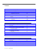
Switch Integration Requirements MAP/40 GPSync Board ED1E43411Grp 175 25-pin male connector GPSync Board RS-232 to RS-449 ED1E43411Grp 304 IDI OUT J2 J1 RS-449 IN DCIU MAP/100 Total distance from switch to Lucent INTUITY system not to exceed 50 ft. System 85 or DEFINITY G2 Figure 1-1.
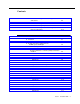
LUCENT INTUITY System Switch Connections System 85 or DEFINITY G2 MAP/40 ED1E43411Grp 304 RS-449 GPSync Board ED1E43411Grp 175 25-pin male connector GPSync Board RS-232 to RS-449 IDI OUT J2 J1 IN DCIU ED1E43411Grp 342 DCIU MAP/100 Total distance from switch to Lucent INTUITY system not to exceed 50 ft. Figure 1-2.
Switch Integration Requirements 1-6 Issue 1 October 1997
Switch Integration Planning 2 Overview This chapter includes worksheets to collect the following information: ■ Voice port information ■ Local and remote switch hunt group information ■ Remote and local data link information ■ Call coverage assignments ■ Hop channel assignments Purpose Before you integrate the Lucent INTUITY™ system with a switch, you must plan the process. This chapter provides worksheets and information to help you plan and record the integration.
Switch Integration Planning General Switch Integration Planning Use Worksheet A (Table 2-1) for general voice port information. Table 2-1. Worksheet A: General Voice Port Information Item Call vectoring used for INTUITY AUDIX? Enter yes or no to indicate whether calls will arrive at the INTUITY AUDIX® system via a VDN and call vector. Number of ports Enter the number of voice ports the INTUITY AUDIX will use.
General Switch Integration Planning Worksheet B: Voice Port Extensions and Names Enter the location, name, and extension for each of the purchased (maximum of 64) voice-ports in the following worksheet (Table 2-2). Date: Prepared By: Contact Telephone Number: Administer the Lucent INTUITY system to have no more than four ports per half-carrier in a traditional module or a universal module that uses TN742s.
Switch Integration Planning Table 2-2.
General Switch Integration Planning Table 2-2. Worksheet B: Voice Port Extensions and Names — Continued LUCENT INTUITY Port Analog Port Equipment Location1 Name2 45 AUDIX 45 46 AUDIX 46 47 AUDIX 47 48 AUDIX 48 49 AUDIX 49 50 AUDIX 50 51 AUDIX 51 52 AUDIX 52 53 AUDIX 53 54 AUDIX 54 55 AUDIX 55 56 AUDIX 56 57 AUDIX 57 58 AUDIX 58 59 AUDIX 59 60 AUDIX 60 61 AUDIX 61 62 AUDIX 62 63 AUDIX 63 64 AUDIX 64 65 AUDIX 65 Extension Continued on next page 1. 2.
Switch Integration Planning Worksheet C: Assign the INTUITY AUDIX Split The following information (Table 2-3) is required to define a hunt group (containing the voice port members) for the Lucent INTUITY system voice ports. NOTE: Only the number of ports actually purchased should be administered in the hunt group. Date: Prepared By: Contact Telephone Number: Table 2-3.
General Switch Integration Planning Worksheet D: Assign the Data Link Use this worksheet (Table 2-4) to plan the DCIU (BX.25) data link. NOTE: You should regard the values and terms used in the following table as those used for administering the switch to work with the Lucent INTUITY system. Date: Prepared By: Contact Telephone Number: Table 2-4. Worksheet D: Assign the Data Link Item Your Entry Switch Number Enter the number of the switch to which the Lucent INTUITY system is connected.
Switch Integration Planning Worksheet E: Assign the Call Coverage Path for Subscribers Complete this worksheet (Table 2-5) to define call coverage paths for subscribers. Date: Prepared By: Contact Telephone Number: Table 2-5. Worksheet E: Assign the Call Coverage Path for Subscribers Item Your Entry COS Number for Subscriber Stations Enter the number of the Class of Service subscribers will have. Call Coverage Group Number Enter the number of the call coverage group for subscribers.
DCS Worksheets DCS Worksheets Complete the following worksheets (Table 2-6, Table 2-7, and Table 2-8) if the Lucent INTUITY system operates in a DCS environment. If you have an existing DCS network or if you are installing one, the GBCS Design Center may have designed the DCS network with a Lucent INTUITY system. The worksheets in this section contain the same information the Design Center may have already created.
Switch Integration Planning Worksheet F: Assign a DCS Remote Node Use this worksheet (Table 2-6) to plan the remote DCS nodes. Complete one copy of this worksheet for each remote switch in the DCS network. NOTE: Except where noted, you should regard the values and terms used in the following table as those used for administering a switch that is a remote node in a DCS.
DCS Worksheets Table 2-6. Worksheet F: Assign a DCS Remote Node Item Your Entry DCS Node Link and Channel Enter the number of the DCIU local port (1–64) on the remote switch and its logical channel (1–64). The switch’s local port equals the remote port number and logical channel administered on the host switch. DCS Node Number Enter the DCS node number of the remote switch. This is the switch number administered on the INTUITY AUDIX system.
Switch Integration Planning Worksheet G: Assign a Split at the Remote Switch Use this worksheet (Table 2-7) to plan the split on each remote switch in the DCS network. Date: Prepared By: Contact Telephone Number: Table 2-7. Worksheet G: Assign a Split at the Remote Switch Item Your Entry COS for ACD Split on Remote Switch Enter the COS number of members of the ACD split. Unanswered calls to subscribers on the remote switch will go to coverage to this split.
DCS Worksheets Worksheet H: Assign the Call Coverage Path for Remote Subscribers Complete this worksheet (Table 2-8) to define call coverage paths for subscribers. Date: Prepared By: Contact Telephone Number: Table 2-8. Worksheet H: Assign the Call Coverage Path for Remote Subscribers Item Your Entry COS Number for Remote Subscriber Stations Enter the number of the Class of Service remote subscribers will have.
Switch Integration Planning 2-14 Issue 1 October 1997
Switch Administration 3 Overview This chapter describes how to administer for an INTUITY™ AUDIX® system on a Generic 2 or System 85 switch. See INTUITY Digital Networking 585-310-567 for information on administering the switch for INTUITY AUDIX Digital Networking. For information about what equipment is required on the Generic 2 or System 85 switch to work with the INTUITY AUDIX system, see INTUITY Messaging Solutions Release 4 System Description, 585-310-235.
Switch Administration ■ DEFINITY Manager IV Terminal Change Management Operations, 585-223-701 ■ DEFINITY Manager IV System Administration, 585-223-700 Assign Voice Ports and the INTUITY AUDIX System ACD Split This section provides information about Call Vectoring and procedures to assign: ■ A new class of service (COS) to the extension numbers ■ The extension numbers to each voice port ■ The Automatic Call Distribution (ACD) split In the following procedures, you will identify each INTUITY AUDIX
Assign Voice Ports and the INTUITY AUDIX System ACD Split Table 3-1.
Switch Administration Table 3-1.
Assign Voice Ports and the INTUITY AUDIX System ACD Split Set Modes for Administration Changes Set the mode of the administration tool to the maintenance, administration, and tape modes. To do this, press M and enter 1 2 3. Assign a New Class of Service (COS) to Extension Numbers Assign a class of service (COS) (1–63) to every extension assigned to the INTUITY AUDIX system.
Switch Administration Assign Extension Numbers to Each Voice Port 000 Word 1 Assign an extension number to each voice port using the COS from Procedure 010, Word 1, Field 1. Field Manager II Field Name Enter 1 Extension [extension]1 2-6 Module, Cabinet, Carrier, Slot, Circuit 2 7 Class of Service [COS]3 8 Port Type 1 1. 2. 3. From Worksheet B: Voice Port Extensions and Names Enter the equipment location of the switch line circuit wired to the INTUITY AUDIX system voice port 1.
Assign Voice Ports and the INTUITY AUDIX System ACD Split 000 Word 3 Administer the bearer capability class of service for each voice port. Field Manager II Field Name Enter 1 Extension [extension]1 5 Bearer Capability Class of Service 0 1. Enter the extension number assigned to the INTUITY AUDIX system voice port number 1. Press ADD and EXECUTE . Repeat Procedure 000 Word 3 for the other voice port extension numbers.
Switch Administration 026 Word 1 Administer the split characteristics for the ACD feature. Field Manager II Field Name Enter 1 ACD Split [split #]1 2 Split Size [number of ports in one of these increments: 16,32,48, 64] 4 Queuing Trunk Group [queue trunk group #]1 8 Inflow Level 02 9 Hunt Type 0 or 2 10 Split Type 2 11 Machine Number [INTUITY AUDIX system machine #]1, 3 1. 2. 3. From Worksheet C: Assign the INTUITY AUDIX Split. If Call Vectoring is used, put a dash in this field.
Assign Voice Ports and the INTUITY AUDIX System ACD Split 001 Word 1 Administer the extensions associated with existing extensions. These associated extensions provide access to ACD splits unless your system uses vectoring. NOTE: Do not assign an extension that was assigned already in Procedure 000, Word 1. The INTUITY AUDIX system associated extension should be a Direct Inward Dialing (DID) type so outside users can reach the INTUITY AUDIX system.
Switch Administration 026 Word 2 Administer the ACD split supervisor and QDN. NOTE: If you are using the Call Management System (CMS) to administer splits, busy out the CMS before doing the following procedure. Field Manager II Field Name Enter 1 ACD Split [INTUITY AUDIX system split #]1 2 Supervisory Extension 2 3 Queue Directory Number [INTUITY AUDIX system extension]3 5 Multiple Call Handling - 6 Auto Available - (do not activate) 1. 2. 3.
Assign a Data Link 026 Word 3 Administer the ACD split member characteristics. Field Manager II Field Name Enter 1 ACD Split [INTUITY AUDIX system split #] 2 Member 1 3 Member Extension [extension number of split member 1] Press ADD and EXECUTE after each entry. Repeat Fields 2 and 3 to add the other members of the INTUITY AUDIX system split.
Switch Administration Table 3-2.
Assign a Data Link Table 3-2.
Switch Administration Table 3-2. Data Link Procedure Overview — Continued Step Procedure Field Manager II Field Name Enter 14 261 Word 2 1 Network Adjunct Class 2 2 Network Adjunct Number ntwk adj # 3 Adjunct Extension INTUITY AUDIX system ext/VDN Press Add Continued on next page 1. 2. 3. 4. 5. If Field 2 does not display 0, enter 1 in Field 1 and press CHANGE and EXECUTE to change field 2 to 0.
Assign a Data Link 275 Word 3 Use this procedure to record the local switch number and check the Caller Response Interval and the Coverage Point Don’t-Answer Interval. Field Manager II Field Name Action 3 Caller Response Interval 1 4 Coverage Point DA Interval 2 8 Local Switch Number Record this number (if dashed, record 1) 10 Call Control FRL Record this number. 1. 2. From Worksheet D: Assign the Data Link. Verify that this is set to the correct number of 2-sec intervals.
Switch Administration Assign a Link 256 Word 1 Administer the characteristics to a DCIU link. 1. Set Field 1 (Link) to the [INTUITY AUDIX system link #]. 2. Press DISPLAY and EXECUTE . At this point, Field 2 should equal 0. Field Manager II Field Name Enter 2 Link Assigned (the AUDIX link) 1 (assumed) 3 Baud Rate 6 4 Local DTE/DCE 0 5 Dial Up 0 6 Protocol 1 7 Destination Machine Type 3 8 Destination Machine Number [INTUITY AUDIX system machine #]1 1.
Assign a Data Link 256 Word 2 Administer the DCIU link BX.25 level-2 timers and counters. Field Manager II Field Name Enter 1 Link (DCIU physical link) [INTUITY AUDIX system link # (1-8)]1 2 Retransmission Timer 1 3 Idle Timer 10 4 Maximum Retransmissions 2 5 Maximum Unacknowledged Frames 7 1. From Worksheet D: Assign the Data Link. Press CHANGE and EXECUTE . 256 Word 3 Administer the DCIU link BX.25 level -3 timers and counters.
Switch Administration 257 Word 5 Administer port reservations for DCIU translations. Field Manager II Field Name Enter 1 Port Number 1 2 Application Type 13 3 Instance Number [INTUITY AUDIX system machine #] 1. From Worksheet D: Assign the Data Link. Enter the INTUITY AUDIX system local port number (same as assigned in Word 2). The recommended number should be 59, 60, 61, or 62. Press CHANGE and EXECUTE . Verify the following switch maintenance ports: 1. Set Field 1 to 6. 2.
Assign a Data Link 257 Word 2 Administer DCIU ports for the network channels. Field Manager II Field Name Enter 1 Local Port (administered as the switch port on the INTUITY system) 591 2 Remote Port (logical channel on the INTUITY system) 1 1. From Worksheet D: Assign the Data Link. Possible range is 1 to 62. Press CHANGE and EXECUTE . Verify the following switch maintenance ports: 1. Set Field 1 (Local Port) to 6. 2. Press DISPLAY and EXECUTE . 3.
Switch Administration 257 Word 1 Administer the components, priority, and alternate routing status of DCIU network channels. Field Manager II Field Name Enter 1 Channel A — Link (switch) 0 2 Channel A — Logical Channel (local port) 1 3 Channel B — Link (switch) [INTUITY AUDIX system link #, normally 1] 4 Channel B — Logical Channel (remote port) 2 5 Priority 1 6 Alternate Routing Flag 0 7 Table Indicator 0 1. 2. From Worksheet D: Assign the Data Link.
Assign a Data Link 258 Word 1 Copy the scratch pad translation tables (temporary tables) to the DCIU machine-used tables. This is used after all DCIU translation changes have been made. Field Manager II Field Name Enter 1 Reboot DCIU 1 2 Configuration 1 1. Verify that this field equals 1. (This verifies the old translations in the scratch pad tables are protected.) Press CHANGE and EXECUTE . NOTE: ChanTran reboots all DCIU links.
Switch Administration Administer and Call Transfer Into INTUITY AUDIX 350 Word 2 Administer the dial access codes (DACs). Field Manager II Field Name Enter 1 Feature 58 2 1st digit [0–9] 3 2nd digit [0–9] 4 3rd digit [0–9] 5 4th digit [0–9] Press ADD and EXECUTE . 261 Word 1 Administer the external adjunct message format.
Assign a Data Link Field Manager II Field Name Enter 1 Network Adjunct Class 2 2 Network Adjunct Number [network adjunct #]1 3 Adjunct Extension [INTUITY AUDIX system extension or VDN]2 1. 2. From Worksheet D: Assign the Data Link. This is the same as Word 1, Field 7. From Worksheet C: Assign the INTUITY AUDIX Split Press ADD and EXECUTE . Save New Translations Perform a Run Tape to save the new translations.
Switch Administration External Loop Test Set the data module for a loopback test: ■ If a Data Service Unit (DSU) is used, press the LL button. NOTE: Lucent Technologies does not officially support the DSU connection While still on Test 3 of Procedure 650: 1. Enter 1 in Field 7. 2. Press EXECUTE 3. Press STOP 4. Press RLS^BUSY^OUT after 8000 bits are sent. . If either of these tests fail, see the switch maintenance manual for procedures to correct the fault.
DCS Administration 4 Overview Purpose The INTUITY™ AUDIX® system can serve more than one switch when the switches are part of a network such as the Lucent Technologies Distributed Communications System (DCS). The switch that hosts the INTUITY AUDIX system connects it to the other switches in the network. The INTUITY AUDIX system uses the switch’s existing DCS trunks for both data and voice communication.
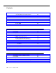
DCS Administration Data Link Administration Figure 4-1 shows that DCS switch data connections involves a distant switch, a host switch, and an INTUITY AUDIX system. Some coordination is required here when assigning port and channel numbers as described after this figure. NOTE: The GBCS Design Center can assist you when designing a multinode INTUITY AUDIX DCS system.
Assign a DCS Remote Node Assign a DCS Remote Node Use the following steps (Table 4-1) to assign an INTUITY AUDIX system switch port at the remote node. This switch processor port is assigned to a spare channel on the DCS link connected to the INTUITY AUDIX system host. Table 4-1.
DCS Administration Table 4-1.
Assign a DCS Remote Node DCS Remote Node Procedures The following sections explain the procedures outlined in Table 4-1. 257 Word 5 Assign the port application. Field Manager II Field Name Enter 1 Port Number [switch port]1 2 Application Type 13 3 Instance Number [INTUITY AUDIX machine #]2 1. 2. From Worksheet D: Assign the Data Link From Worksheet C: Assign the INTUITY AUDIX Split Press CHANGE and EXECUTE . 257 Word 2 Assign the local/remote port pairing.
DCS Administration 257 Word 1 Assign the INTUITY AUDIX system switch port to the DCS link and channel. Field Manager II Field Name Enter 1 Component A — Link (switch) 0 2 Component A — Logical Channel (local port) [switch port 1–64]1 3 Component B — Link (switch) [DCS node link 1–8]1 4 Component B — Logical Channel (local port) [DCS channel 1–64]1,2 5 Priority 1 6 Alternate Routing Flag 0 1. 2. From Worksheet F: Assign a DCS Remote Node.
Assign a DCS Remote Node 261 Word 1 Associate the internal AUDIX number with the network AUDIX number. Field Manager II Field Name Enter 1 Local Adjunct 2 2 Local Adjunct Number [1–8] 3 Local Adjunct Type 3 4 Version Number - 5 N-digit format - 6 N-digit scrolling - 7 Network Adjunct Number [1–99] Press CHANGE and EXECUTE . 261 Word 2 Administer the external network adjunct extension.
DCS Administration 258 Word 1 Update the DCIU’s on-line translations. Field Manager II Field Name Enter 1 Reboot DCIU 1 Press CHANGE and EXECUTE . 258 Word 2 Refresh the DCIU’s scratch pad. Field Manager II Field Name Enter 1 Copy Tables 1 Press CHANGE and EXECUTE . Save New Translations Perform a Run Tape to save the new translations. If the system has a duplicated common control, the Run Tape operation will update both tapes.
Assign an ACD Split at the Remote Switch Table 4-2.
DCS Administration Voice Port Access Procedures The following sections explain the procedures outlined in Table 4-2. 010 Word 1 Set up a COS for the ACD members. Field Manager II Field Name Enter 1 Class of Service [COS]1 5 Follow Me 1 15 Touch-tone dialing 1 20 ACD Member 1 1. From Worksheet G: Assign a Split at the Remote Switch Press CHANGE and EXECUTE . 000 Word 1 Assign an extension number for ACD member 0.
Assign an ACD Split at the Remote Switch 100 Word 1 Assign a queue trunk group for the ACD. Field Manager II Field Name Enter 1 Trunk Group [queuing trunk group #]1 6 Trunk Type 6 1. From Worksheet G: Assign a Split at the Remote Switch Press ADD and EXECUTE . 026 Word 1 Assign the ACD.
DCS Administration 001 Word 1 Assign extensions associated with existing extensions to provide access to the ACD split. Field Manager II Field Name Enter 1 Primary Extension [member 0 extension]1 2 Associated Extension [DCS INTUITY AUDIX system extension]1 1. From Worksheet G: Assign a Split at the Remote Switch Press ADD and EXECUTE . Error code 12 is displayed if the extension number is already assigned as an extension number. Do not remove this extension if it is a working station.
Assign a Hop Channel 026 Word 3 Administer ACD split member characteristics. Field Manager II Field Name Enter 1 ACD Split [DCS INTUITY AUDIX system split]1 2 Member 1–63 3 Member Extension [member 0 extension] 1. From Worksheet G: Assign a Split at the Remote Switch. Press ADD and EXECUTE . Go to the attendant console (if you are on the customer premises) and Call Forward the supervisor extension to the INTUITY AUDIX system QDN at the remote location.
DCS Administration Hop Channel Procedure Overview — Continued Table 4-3. Step Procedure Field Manager II Field Name Enter Press 6 Alternate Routing Flag 0 Add 3 258 Word 1 1 Reboot DCIU 1 Change 4 258 Word 2 1 Copy Tables 1 Change Continued on next page 1. If Field 2 does not display 0, enter 1 in Field 1 and press 2 to 0. CHANGE and EXECUTE to change field Hop Channel Procedures The following sections explain the procedures outlined in Table 4-3.
Save New Translations 257 Word 1 Assign the hop. Field Manager II Field Name Enter 1 Component A — Link (switch) [DCS host link]1 2 Component A — Logical Channel (local port) [DCS channel]1 3 Component B — Link (switch) [INTUITY AUDIX system link]1 4 Component B — Logical Channel (local port) [INTUITY AUDIX system channel]1 5 Priority 1 6 Alternate Routing Flag 0 1. From Worksheet D: Assign the Data Link. Press ADD and EXECUTE . 258 Word 1 Update the DCIUs on-line translations.
DCS Administration Subscriber Administration on the Remote Node Assign those subscribers at this DCS node (Table 4-4). Subscribers on the host node can use Call Coverage, Send All Calls, LWC, Enhanced Call Transfer, and Call Forwarding. Table 4-4.
Subscriber Administration on the Remote Node Table 4-4. Subscriber Administration on Remote Node Overview — Continued Step Procedure Field Manager II Field Name Enter Press 6 261 Word 1 1 Local Adjunct Class 2 Add 2 Local Adjunct Number 1 3 Local Adjunct Type 3 7 Network Adjunct Number net adj # 1 Network Adjunct Class 2 2 Network Adjunct Number net adj # 3 Adjunct Extension INTUITY AUDIX system ext # 7 261 Word 2 Change Continued on next page 1.
DCS Administration 011 Word 1 Add a coverage group with the INTUITY AUDIX system as the coverage point. Field Manager II Field Name Enter 1 Call Coverage Group [group #]1 2 Extension Activity 12 7 Coverage Point Indicator 13 8 Coverage Point 1 (must be the last coverage point) 9 Coverage Point Ext/ACD Split/VDN [DCS INTUITY AUDIX system split]4 1. 2. 3. 4. From Worksheet H: Assign the Call Coverage Path for Remote Subscribers.
Subscriber Administration on the Remote Node 063 Word 1 Assign Message Waiting. Field Manager II Field Name Enter 1 Extension [extension #] 2-6 Module, Cabinet, Carrier, Slot, Circuit [equipment location] 7 Device Type [device type]1 8 Member (button) [member]1 1. From Worksheet H: Assign the Call Coverage Path for Remote Subscribers. For more information about these fields, see the appropriate Generic 2 or System 85 administration manual. Press ADD and EXECUTE .
DCS Administration 261 Word 1 Assign Call Transfer Into INTUITY AUDIX. Field Manager II Field Name Enter 1 Local Adjunct Class 2 2 Local Adjunct Number 1 3 Local Adjunct Type 3 7 Network Adjunct Number [1–99] Press ADD and EXECUTE . 261 Word 2 Administer the external network adjunct extension. Field Manager II Field Name Enter 1 Network Adjunct Class 2 2 Network Adjunct Number 1 3 Adjunct Extension [INTUITY AUDIX system extension]2 1. 2.
Lucent INTUITY System Administration for Switch Integration 5 Overview This chapter describes how you administer the Lucent INTUITY system for integration with the switch. Use the Switch Interface Administration screen to enter the required information. Purpose In addition to administering the System 85 or G2 switch to work with the Lucent INTUITY™ system, you must administer the Lucent INTUITY system to work with the switch.
Lucent INTUITY System Administration for Switch Integration Administer the Lucent INTUITY System for a Non-DCS Switch Integration Use the instructions in this section to administer the Lucent INTUITY system for a non-DCS switch integration. If you need to integrate your Lucent INTUITY system with a DCS network, skip this section and continue with ‘‘Administer the Lucent INTUITY System for a DCS Network Switch Integration’’.
Administer the Lucent INTUITY System for a Non-DCS Switch Integration 5. Select DCIU Interface Administration (at the Switch Interface Administration menu). The system displays the DCIU Interface Administration window (Figure 5-2). Figure 5-2. DCIU Interface Administration Window When you access the screen, the cursor appears in the Extension Length field. (The Switch Link Type and Switch Release fields are display only.
Lucent INTUITY System Administration for Switch Integration 10. Press SAVE to update the system with the changes you entered. The system displays the following message Update successful to indicate that the switch link is resetting. 11. Press CANCEL to exit the Switch Interface Administration screen and return to the Lucent INTUITY System Main menu (Figure 5-1). 12. You have completed the Lucent INTUITY system administration required for a DCIU switch integration.
Administer the Lucent INTUITY System for a DCS Network Switch Integration 4. Enter the number of the host switch in the Host Switch Number: field. Valid host switch numbers range from 1 to 20. 5. Enter the logical channel number in the AUDIX Port Logical Channel field. Logical channels range from 1 to 64. The logical channel is the same number as the Interface Link and the Local DCIU Port Number on the switch.
Lucent INTUITY System Administration for Switch Integration 5-6 Issue 1 October 1997
Acceptance Test Administration 6 Overview At some point in the acceptance tests given in the installation documents, you will be asked to assign call coverage to test stations. This chapter describes how to perform administration on the switch for a post-installation acceptance test. Purpose Here, test telephones are administered in the usual way so that a test of their capabilities reflects the way working stations will act when they are given access to the INTUITY system.
Acceptance Test Administration finish tests given in the installation document. You must perform the following two tasks to administer a System 85 or DEFINITY® G2 switch for acceptance tests. ■ Administer the coverage path ■ Administer the test subscriber stations Use ordinary System 85 or DEFINITY® G2 methods to administer two test subscribers for acceptance tests. After administering the test subscribers, continue with the procedures in this chapter to administer the switch for acceptance tests.
Assign Switch Features for INTUITY AUDIX System Subscribers Table 6-1.
Acceptance Test Administration 010 Word 1 Administer the features assigned to a station line class of service (COS). Field Manager II Field Name Enter 1 Class of Service [COS] 4 Busy and Don’t Answer 1 5 Follow Me 1 14 Conference 3-Party/Transfer 1 15 Touch-Tone Dialing 1 Press CHANGE and EXECUTE . 010 Word 2 Administer the LWC—Origination and LWC—Termination to a COS. Field Manager II Field Name Enter 1 Class of Service [COS]1 2 Originating 1 3 Terminating 1 1.
Assign Switch Features for INTUITY AUDIX System Subscribers 011 Word 1 Administer the criteria, principle don’t answer interval, and coverage points of a call coverage group. Field Manager II Field Name Enter 1 Call coverage Group [group split #]1 2 Extension Active 0 or nonzero #2 7 Coverage Point Indicator 13 7 ACD Split Indicator 13 8,9, or 10 Coverage Point;[INTUITY AUDIX system split]4 1. 2. 3. 4. If using Call Vectoring, enter the Call Coverage Group Number.
Acceptance Test Administration Add the Test Subscriber Stations After you administer the call coverage path, you must add the test subscriber stations. Each subscriber station must contain the correct information for the Lucent INTUITY system to operate. 000 Word 1 Assign an extension number to each voice port using the COS from Procedure 010.
Assign Switch Features for INTUITY AUDIX System Subscribers Assign AMW 063 Word 1 Assign the Automatic Message Waiting (AMW) feature to a straight line set. Field Manager II Field Name Enter 1 Extension [extension] 2–6 Module, Cabinet, Carrier, Slot, Circuit [equipment location] 7 Device Type [device type]1 8 Member (button) [member]1 1. For more information about these fields, see the appropriate Generic 2 or System 85 administration manual. Press ADD and EXECUTE .
Acceptance Test Administration 6-8 Issue 1 October 1997
Cut-to-Service Administration 7 Overview At some point in the cut to service procedures given in the installation documents, you will be asked to assign call coverage to your user’s stations. This chapter describes how to perform this task on your switch. Purpose Here, subscribers stations are administered so that they are members of a class of service that has call coverage assigned to INTUITY messaging.
Cut-to-Service Administration administration, and acceptance tests must be completed before you cut the system into service. To perform the cut-to-service process, you must perform the following two tasks: ■ Administer the coverage path. ■ Administer the subscriber stations. Continue with the procedures in this chapter to administer the switch for the cut-to-service. Use the following procedures to cut the Lucent INTUITY system into service.
Assign Switch Features for INTUITY AUDIX® System Subscribers Table 7-1.
Cut-to-Service Administration Assign a New COS and New Call Coverage Group to Test Subscribers Define a call coverage path for subscribers with the Lucent INTUITY hunt group as a coverage point. You may need to define several call coverage paths depending on how the customer wants to handle call coverage for groups of subscribers. If the Lucent INTUITY system has been integrated with an existing switch, you may need to add the Lucent INTUITY hunt group as another coverage point for existing coverage paths.
Assign Switch Features for INTUITY AUDIX® System Subscribers 011 Word 1 Administer the criteria, principle don’t answer interval, and coverage points of a call coverage group. Field Manager II Field Name Enter 1 Call coverage Group [group split #]1 2 Extension Active 0 or 1 2 7 Coverage Point Indicator 13 7 ACD Split Indicator 13 8,9, or 10 Coverage Point;[INTUITY AUDIX system split]4 1. 2. 3. 4. If using Call Vectoring, enter the Call Coverage Group Number.
Cut-to-Service Administration 000 Word 1 Assign an extension number to each voice port using the COS from Procedure 010. Field Manager II Field Name Enter 1 Extension [extension #]1 2–6 Module, Cabinet, Carrier, Slot, Circuit [equipment location] 7 Class of Service [COS] 1. This must be the same length as the extension numbers assigned to the INTUITY AUDIX voice ports. Press ADD and EXECUTE . Repeat Procedure 000, Word 1 for the next voice terminal.
Assign Switch Features for INTUITY AUDIX® System Subscribers Assign AMW 063 Word 1 Assign the Automatic Message Waiting (AMW) feature to a straight line set. Field Manager II Field Name Enter 1 Extension [extension] 2–6 Module, Cabinet, Carrier, Slot, Circuit [equipment location] 7 Device Type [device type]1 8 Member (button) [member]1 1. For more information about these fields, see the appropriate Generic 2 or System 85 administration manual. Press ADD and EXECUTE .
Cut-to-Service Administration 7-8 Issue 1 October 1997
Optional Feature Administration 8 Overview This chapter describes how to assign Automated Attendant, Call Transfer, Switch Recorded Announcement, and Switch Multiple Coverage Paths on Generic 2 or System 85. Purpose Use this chapter to enable on the switch features available to your copy of INTUITY™ Messaging Solutions. Automated Attendant Administration Automated Attendant is an INTUITY™ AUDIX® system feature that provides a caller with menu options.
Optional Feature Administration Automated Attendant Substitute Strategies A substitute for Automated Attendant is needed so that calls do not go unanswered when the INTUITY AUDIX system is busy. Each INTUITY AUDIX system must be individually tailored. Consult with your Lucent Technologies representative before using the following suggestions. Assign the Automated Attendant extension to a real voice terminal, member 0 in an ACD split. Call forward the extension to AUDIX. For R2V4 1.0, assign a new vector.
Transfer into INTUITY AUDIX Transfer into INTUITY AUDIX This feature allows an attendant (or other party) to transfer a caller who has been sent to coverage (or otherwise redirected) back to the INTUITY AUDIX system to record a message. Table 8-1 provides an overview of the procedures. Table 8-1.
Optional Feature Administration 350 Word 2 Assign a DAC to feature code 58. Field Manager II Field Name Enter 1 Feature 58 2 Digit 1 [first # of DAC] 3 Digit 2 [second # of DAC] 4 Digit 3 [third # of DAC] 5 Digit 4 [fourth # of DAC] Press ADD and EXECUTE . 261 Word 1 Assign the INTUITY AUDIX system machine to a network adjunct number.
Transfer into INTUITY AUDIX 000 Word 2 Assign each extension to activate the Transfer into INTUITY AUDIX feature in the extension’s coverage path. Do the following procedure for each user extension with this feature. Field Manager II Field Name Enter 9 LWC Destination 31 10 INTUITY AUDIX [INTUITY AUDIX system machine #] 1. This field is optional. Assign it if the users want LWC messages sent and stored in the INTUITY AUDIX system instead of the switch. Press ADD and EXECUTE .
Optional Feature Administration Recorded Announcement at the Switch Use the following procedures (Table 8-2) to provide a recorded announcement at the switch for anyone who accesses the INTUITY AUDIX system, either through a direct call or call redirection. The announcement is heard when all INTUITY AUDIX system voice ports are busy and calls start entering the INTUITY AUDIX system queue. Table 8-2.
Switch Multiple Coverage Paths 150 Word 1 Assign an announcement system to the INTUITY AUDIX system queue trunk group. Field Manager II Field Name Enter 1– 5 Module, Cabinet, Carrier, Slot, Circuit [announcement eq loc] 6 Trunk Group [Q trunk group] Press ADD and EXECUTE . 027 Word 1 Assign an announcement system to the INTUITY AUDIX system ACD group.
Optional Feature Administration Table 8-3.
Switch Multiple Coverage Paths 011 Word 1 Administer the Coverage Group and Characteristics fields. Field Manager II Field Name Enter 1 Call Coverage Group 1 2 Extension Active 2 3 Extension Busy 2 4 All Calls 2 5 Don’t Answer 2 1. 2. For Path 1, enter the even group number assigned in Procedure 000, Word 2, Field 1. For Path 2, enter the odd group number assigned in Procedure 000, Word 2, Field 1.
Optional Feature Administration Table 8-4.
Switch Administration for the Lucent INTUITY Lodging System A Overview At this point in the installation, you have completed the switch integration procedures required to integrate the switch with the basic Lucent INTUITY system. If the Lucent INTUITY system includes the optional lodging feature, you must now perform additional switch administration as outlined in this chapter.
Switch Administration for the Lucent INTUITY Lodging System 2. Have the voice ports on the Lucent INTUITY MAP computer wired to the switch ports that terminate the hunted extensions. Wire them as described in Installation book for your platform. Message-Retrieval Administration The message-retrieval number is a telephone number that subscribers call to retrieve voice-mail messages. Like other calls to the Lucent INTUITY system, message-retrieval calls ultimately go to the Lucent INTUITY hunt group.
Voice Mail Administration 1. Administer on your switch an extension number that is not associated with a switch port. (These are often called phantom or dummy numbers.) This number is to be used to retrieve messages from a remote telephone. 2. Configure this number so that the Lucent I NTUITY hunt group is in its coverage path for all calls. 3. If your switch has a password capability, assign a password to the new extension. 4. Assign the service ldg_ni_vmto the new extension. a.
Switch Administration for the Lucent INTUITY Lodging System To provide such a service: 1. Administer on your switch an extension number that is not associated with a switch port. (These are often called phantom or dummy numbers.) This number is to be used to send voice messages to your subscribers. 2. Configure this number so that the Lucent INTUITY hunt group is in its coverage path for all calls. 3. Assign the service ldg_ni_vmto the new extension. a. Log in to the Lucent INTUITY system as sa or craft.
Do Not Disturb subscriber’s extension and treats the call as one to be answered and recorded. Depending on how the extension is listed, the call may be answered by either the AUDIX or Lodging application. 1. Administer your switch to assign call coverage to the Lucent INTUITY hunt group number for each guest’s extension. Do Not Disturb Look for features on your switch that adapt themselves especially well to lodging situations. One example is the Do Not Disturb feature on some switches.
Switch Administration for the Lucent INTUITY Lodging System The advantages of this method include: ■ Attendants can learn to cope with the new system without having to answer the questions of large numbers of guests. ■ No guest has to learn both the old system and the new one. Current guests use the old system, new guests use the Lucent INTUITY Lodging system. ■ You can assign custom passwords and language options to each guest as the guest is checked in.
Glossary GL Numerics 5ESS Switch A central office switch manufactured by Lucent Technologies that can be integrated with the Lucent INTUITY™ system. A accessed message A message that was received and scanned (either the entire message or just the header). ACA See automatic circuit assurance (ACA). ACD See automatic call distribution (ACD). activity menu The list of options spoken to users when they first access a messaging system. Selecting an activity is the starting point for all user operations.
Glossary alarms Hardware, software, or environmental problems that may affect system operation. Alarms are classified as major, minor, or warning. alphanumeric Consisting of alphabetic and numeric symbols or punctuation marks. ALT See assemble, load, and test (ALT). American wire gauge (AWG) A standard measuring gauge for nonferrous conductors. AMIS See Audio Messaging Interchange Specification (AMIS).
Glossary ASP advanced signal processor asynchronous communication A method of data transmission in which bits or characters are sent at irregular intervals and spaced by start and stop bits rather than time. See also synchronous communication. asynchronous data unit (ADU) An electronic communications device that can extend data transmission over asynchronous lines more than 50 feet in length. Recommended ADUs for use with the Lucent INTUITY system include Z3A1 or Z3A4.
Glossary automatic message scan An INTUITY AUDIX feature that allows users to scan all message headers and messages at the touch of two buttons. With Lucent INTUITY FAX Messaging, this feature allows all new faxes to be bundled and transmitted over a single fax call delivery call. Also called autoscan. autoprint An INTUITY AUDIX feature that allows users to designate that faxes be automatically sent to a specified print destination. autoscan See automatic message scan. AWG See American wire gauge (AWG).
Glossary boot The operation to start a computer system by loading programs from disk to main memory (part of system initialization). Booting is typically accomplished by physically turning on or restarting the system. Also called reboot. boot filesystem The filesystem from which the system loads its initial programs. BRI See basic rate interface (BRI). broadcast messaging An INTUITY AUDIX feature that enables the system administrator and other designated users to send a message to all users automatically.
Glossary callback number In AMIS analog networking, the telephone number transmitted to the recipient machine to be used in returning messages that cannot be delivered. call classification analysis (CCA) A process that enables application designers to use information available within the system to classify the disposition of originated and transferred calls. call coverage A switch feature that defines a preselected path for calls to follow if the first (or second) coverage points are not answered.
Glossary cartridge tape drive A high-capacity data storage/retrieval device that can be used to transfer large amounts of information onto high-density magnetic cartridge tape based on a predetermined format. This tape is to be removed from the system and stored as a backup. CAS See call accounting system (CAS). CCA See call classification analysis (CCA). CDH See call data handler process (CDH). CDR See call detail recording (CDR).
Glossary CNG tone See calling tone (CNG tone). CO See central office (CO). COR See class of restriction (COR). COS See class of service (COS). code excited linear prediction (CELP) An analog-to-digital voice coding scheme. collocated A Lucent INTUITY system installed in the same physical location as the host switch. See also local installation.
Glossary coverage path The sequence of alternate destinations to which a call to a user on a Lucent INTUITY system is automatically sent when it is not answered by the user. This sequence is set up on the switch, normally with the Lucent INTUITY system as the last or only destination. CPU See central processing unit (CPU). cross connect Distribution-system equipment used to terminate and administer communication circuits.
Glossary DBP See data base processor. DCE See data communications equipment (DCE). DCIU See data communications interface unit (DCIU). DCP See digital communications protocol (DCP). DCS See distributed communications system (DCS). debug See troubleshooting. dedicated line A communications path that does not go through a switch. A dedicated (hard-wired) path can be formed with directly connected cables.
Glossary DID See direct inward dialing (DID). digital communications protocol (DCP) A 64-Kbps digital data transmission code with a 160-Kbps bipolar bit stream divided into two information (I) channels and one signaling (S) channel. digital networking A method of transferring messages between messaging systems in a digital format. See also INTUITY AUDIX Digital Networking.
Glossary DTMF See dual tone multifrequency (DTMF). dual in-line package (DIP) switch A small switch, usually attached to a printed circuit card, in which there are only two settings: on or off (or 0 or 1). DIP switches are used to configure the card in a semipermanent way. dual language greetings The capability of INTUITY AUDIX users to create personal greetings in two different languages— one in a primary language and one in a secondary language.
Glossary enhanced serial data interface (ESDI) A software-controlled and hardware-controlled method used to store data on magnetic peripherals. equipped/unequipped The state of a networking channel that indicates whether Lucent INTUITY software has recognized it. Devices must be equipped before they can be enabled (made active). See also enabled/disabled. error message A message on the screen indicating that something is wrong within the system and possibly suggesting how to correct it.
Glossary fax addressing prefix Uniquely identifies a particular fax nodepoint to the Lucent INTUITY system. Used by the system as a “template” to differentiate all call-delivery machines on the network from each other. fax endpoint Any device capable of receiving fax calls. Fax endpoints include fax machines, individual PC fax modems, fax ports on LAN fax servers, and ports on fax-enabled messaging systems.
Glossary function Individual steps or procedures within a mailbox activity. function key (F key) A key on a computer keyboard programmed to perform a defined function when pressed. The user interface for the Lucent INTUITY system defines keys F1 through F8. FX See foreign exchange (FX). G Generic 1, 2, or 3 Lucent switch system software releases, designed for serving large communities of System 75 and System 85 users.
Glossary help A command run by pressing HELP or CTRL ? on a Lucent INTUITY display terminal to show the options available at your current screen position. In the INTUITY AUDIX system, press * H on the telephone keypad to get a list of options. See also on-line help. host switch The switch directly connected to the Lucent INTUITY system over the data link. Also, the physical link connecting a Lucent INTUITY system to a distributed communications system (DCS) network.
Glossary internal e-mail Software on a PC that provides messaging capability between users on the same AUDIX system, or to administered remote AUDIX systems and users. Users can create, send, and receive a message that contains multiple media types; specifically, voice, fax, text, or file attachments (software files, such as a word processing or spreadsheet file).
Glossary K L label The name assigned to a disk device (either a removable tape cartridge or permanent drive) through software. Cartridge labels may have a generic name (such as “3.3”) to show the software release, or a descriptive name if for back-up copies (such as “back01”). Disk drive labels usually indicate the disk position (such as “disk00” or “disk02”). LAN See local area network (LAN).
Glossary local network An INTUITY AUDIX Digital Network in which all Lucent INTUITY systems are connected to the same switch. login A unique code a user must enter to gain approved access to the Lucent INTUITY system. See also password. login announcement A feature enabling the system administrator and other designated users to create a mail message that is automatically played to all INTUITY AUDIX users every time they log in to the system.
Glossary media type The form a message takes. The media types supported by the Lucent INTUITY system are voice, text, file attachments, and fax. memory A device that stores logic states such that data can be accessed and retrieved. Memory may be temporary (such as system RAM) or permanent (such as disk). menu A list of options displayed on a computer terminal screen or spoken by a voice processing system. Users choose the option that reflects what action they want the system to take.
Glossary mode code A string of touch-tones from a MERLIN LEGEND switch. A mode code may send the INTUITY AUDIX system information such as call type, calling party, called party, and on/off signals for message waiting indicators. modem A device that converts data from a form that is compatible with data processing equipment (digital) to a form compatible with transmission facilities (analog), and vice-vera.
Glossary NT Networking application identifer. See application identifer. MWL See message waiting lamp (MWL). numbering plan area Formal name for 3-digit telephone area codes in North America. Within an area code, no two telephone lines may have the same 7-digit phone number. The code is often designated as NXX, to indicate the three digits. O off-hook See switch hook. on-hook See switch hook.
Glossary P parallel transmission The transmission of several bits of data at the same time over different wires. Parallel transmission of data is usually faster than serial transmission. password 1. A word or character string recognized automatically by the Lucent INTUITY system that allows a user access to his/her mailbox or a system administrator access to the system data base. 2. An alphanumeric string assigned to local and remote networked machines to identify the machines or the network.
Glossary priority call answer An INTUITY AUDIX feature that allows users to designate a call answer message as a priority message. To make a message a priority message, the caller presses 2 after recording. priority messaging An INTUITY AUDIX feature that allows some users to send messages that are specially marked and preferentially presented to recipients. See also priority outcalling.
Glossary R RAM See random access memory (RAM). random access memory (RAM) The memory used in most computers to store the results of ongoing work and to provide space to store the operating system and applications that are actually running at any given moment. read-only memory (ROM) A form of computer memory that allows values to be stored only once; after the data is initially recorded, the computer can only read the contents.
Glossary request to send (RTS) One of the control signals on an EIA-232 connector that places the modem in the originate mode so that it can begin to send. restart 1. A Lucent INTUITY feature that allows INTUITY AUDIX users who have reached the system through the call answer feature to access their own mailboxes by entering the * R (Restart) command. This feature is especially useful for long-distance calls or for users who want to access the Lucent INTUITY system when all the ports are busy. 2.
Glossary screen That portion of the Lucent INTUITY user interface through which most administrative tasks are performed. Lucent INTUITY screens request user input in the form of a command from the enter command: prompt. SCSI See small computer systems interface (SCSI). secondary extension A second, fax-dedicated extension that directs incoming faxes directly into a user’s mailbox without ringing the telephone.
Glossary SSP scaleable signal processor station message desk interface (SMDI) See simplified message desk interface (SMDI). station message detail recording See call detail recording (CDR). subscriber A Lucent INTUITY user who has been assigned the ability to access the INTUITY AUDIX Voice Messaging system. surge A sudden rise and fall of voltage in an electrical circuit.
Glossary synchronizer The name given to the trusted server by the e-mail vendor, Lotus Notes. synchronous communication A method of data transmission in which bits or characters are sent at regular time intervals, rather than being spaced by start and stop bits. See also asynchronous communication. synchronous transmission A type of data transmission where the data characters and bits are exchanged at a fixed rate with the transmitter and receiver synchronized.
Glossary terminal type A number indicating the type of terminal from which a user is logging in to the Lucent INTUITY system. Terminal type is the last required entry before gaining access to the Lucent INTUITY display screens. terminating resistor A grounding resistor placed at the end of a bus, line, or cable to prevent signals from being reflected or echoed.
Glossary undelivered message A message that has not yet been sent to an INTUITY AUDIX user’s incoming mailbox. The message resides in the sender’s outgoing mailbox and may be modified or redirected by the sender. unequipped See equipped/unequipped. unfinished message A message that was recorded but not approved or addressed, usually as the result of an interrupted INTUITY AUDIX session. Also called working message.
Glossary voice link The Lucent INTUITY analog connection(s) to a call-distribution group (or hunt group) of analog ports on the switch. voice mail See voice message. voice mailbox See mailbox. voice message Digitized information stored by the Lucent INTUITY system on disk memory. Also called voice mail. voice port The IVC6 port that provides the interface between the Lucent INTUITY system and the analog ports on the switch.
Index IN A Account code undefined, xxix ACD Generic 2, 3-2, 3-7 System 85, 3-2, 3-7 AMW Generic 2, 6-7, 7-7 AMW--System 85, 6-7, 7-7 AUDIX Data Acquisition Package, xxxi Auto dial button programming passwords on, xxvi Automated Attendant, xxii Automated attendant toll fraud, xxi automated attendant substitute strategies, 8-2 switch administration, 8-1 Automatic Message Waiting, see AMW System 85, 3-10, 4-11 COS Generic 2, 6-4, 7-4 System 85, 6-3, 7-4 coverage path Generic 2, 6-4, 7-4 multiple paths, 8-7
Index G O Glossary, GL-1 Outcalling limiting, xxii Outward dialing restrictions, xxii H Hackers and telecommunications fraud, xxi Holding time long, xxx short, xxx hop channel Generic 2, 4-13 System 85, 4-13 hunt group System 85, 4-8 hunt group--Generic 2, 4-8 Password guidelines subscriber, xxv Passwords adjunct, xxvi Port PBX, xxii treated as station, xxii voice mail, xxii R I Intended audiences, xi L LDN Generic 2, 3-9 System 85, 3-9 Leave Word Calling, see LWC LWC Generic 2, 6-4, 7-4 System 85,
Index System 85, 4-16 Subscribers password guidelines, xxv T Tenant Services, xxiv timer Generic 2, 3-17 System 85, 3-17 Toll abusers internal, xxix transfer into Intuity AUDIX, 8-3 Trunk verification, xxv Trunk access code, xxv U Users unauthorized restricting, xxvii V VDN Generic 2, 3-2 System 85, 3-2 Virtual Nodepoint Identifier, xxiv voice mailbox unassigned, xxvi voice port Generic 2, 3-2 System 85, 3-2 Issue 1 October 1997 IN-3
Index IN-4 Issue 1 October 1997