
User`s manual
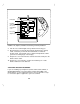

Table Of Contents
- Contents
- Introduction
- Your ISDN 8510T Voice Terminal
- Feature Descriptions
- Voice Features
- Features Accessed with the Display and Softkeys
- ENTERING AND EXITING SOFTKEY MODE (USING THE MENU AND THE EXIT BUTTONS)
- THE VOICE TERMINAL SELF-TEST FEATURE bbbbbbb
- USING THE NEXT, THE PREV, AND THE DIR BUTTONS
- RESPONDING TO ´QUIT´ AND ´DONE´
- A SOFTKEY DISPLAY SCREEN FLOWCHART
- SETTING THE CLOCK
- SETTING THE SPEAKERPHONE
- ADDING, EDITING, AND DELETING A NUMBER AND NAME IN THE DIRECTORY
- VIEWING A DIRECTORY ENTRY (AND PLACING A CALL)
- USING THE DIR BUTTON TO PLACE A CALL
- USING THE CALL LOG
- LOCKING AND UNLOCKING THE DIRECTORY, CALL LOG, AND ALL SOFTKEYS
- CHANGING OR REMOVING YOUR PASSWORD
- SELF-TEST
- CHOOSING THE CONTRAST LEVEL FOR THE DISPLAY
- SELECTING A PERSONALIZED RING
- SETTING THE RATE AT WHICH YOU VIEW THE DISPLAY MESSAGES
- TURNING ON OR OFF SOFTKEY INFORMATION TONES
- SETTING THE NUMBER OF NAMES ON THE DIRECTORY PAGE
- Tones and Their Meanings
- Labeling and Installing the Designation Card and the Telephone Number Card
- Installation
- Technical Description
- Index

Installation
CONTENTS OF THE 8510T PACKAGE
Before you begin, make sure you have the following parts in the box:
8510T voice terminal (with attached desktop stand)
K-type handset
9-foot handset cord
7-foot line cord
Designation card(s)
Cover(s) for Designation card(s)
This user’s manual
A quick reference manual for using the softkeys
DESKTOP INSTALLATION
NOTE: The following instructions describe the installation of the 8510T
voice terminal on a desk or table. If you choose, instead, to mount the
voice terminal on the wall, use the instructions included in the 8510T
Voice Terminal Wall Mounting Kit (COMCODE: 106614894).
IMPORTANT: The tasks of setting the terminal resistor jumpers and the
phantom/auxiliary power jumpers can only be done by qualified service
personnel. DO NOT attempt to remove the voice terminal desktop stand
or set either type of jumpers yourself.
Use the following directions to connect the line cord and adjunct cord to
the appropriate jacks on the voice terminal.
1 Place the voice terminal face down on a flat surface.
2 Using the thumb notches beside the kickstand, lift the kickstand from
the desktop stand.
3 Pass the line cord (and adjunct cord, if applicable) under the
kickstand.
4 Snap one end of the 7-foot line cord into the "LINE" jack and the
adjunct cord (if applicable) into the "ADJUNCT" jack on the bottom of
the voice terminal. See Figure 5 for the location of the jacks. For
more information on installing adjuncts, refer to the section "Attaching
Adjunct Equipment."
68