
Communications System Owner Manual
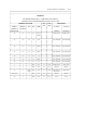


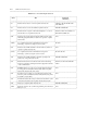
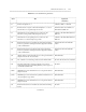
Table Of Contents
- Table of Contents
- ABOUT THIS DOCUMENT
- 1. INTRODUCTION TO CONNECTIVITY
- 2. COMMUNICATION SYSTEM NETWORKING (em AN OVERVIEW
- 3. TANDEM TIE TRUNK NETWORKS
- 4. MAIN-SATELLITE/TRIBUTARY (MS/T) NETWORKS THROUGH THE UDP OR MULTIPREMISES PACKAGES
- 5. ELECTRONIC TANDEM NETWORK (ETN) THROUGH THE ETN AND PNA PACKAGES
- 6. DISTRIBUTED COMMUNICATIONS SYSTEM (DCS)
- 7. DATA CONNECTIVITY - AN OVERVIEW
- 8. DATA COMMUNICATIONS CAPABILITIES
- 9. DATA COMMUNICATIONS CONFIGURATIONS
- A. RELATED DOCUMENTS
- B. SYNCHRONIZATION OF DIGITAL FACILITIES
- THE NEED FOR SYNCHRONIZATION
- SYNCHRONIZATION HIERARCHY
- CHANGES TO THE SCS SOFTWARE MADE AVAILABLE VIA SOFTWARE PATCHES
- NETWORK SYNCHRONIZATION AND ENGIINEERING
- AVAILABILITY OF SYNCHRONIZATION SOURCES
- CONCLUSIONS ON SYNCHRONIZATION
- USE OF GENERIC 2 AS A SYSTEM CLOCK REFERENCE
- USE OF GENERIC 1 AS A SYSTEM CLOCK REFERENCE
- C. TRUNKING TERMS AND CAPABILITIES
- D. COMMUNICATIONS PROTOCOLS
- E. LEAD DEFINITIONS
- F. NETWORKING FEATURES - AVAILABILITY MATRIX
- ABBREVIATIONS
- GLOSSARY
- INDEX
D-2 COMMUNICATIONS PROTOCOLS
_ ___________________________________________________________________________________________________________________________
_ ___________________________________________________________________________________________________________________________
_ ___________________________________________________________________________________________________________________________
OSI MODEL
To provide a model through which all protocols could be classified and studied, the International
Organization for Standardization (ISO) created the Open Systems Interconnection (OSI) architecture.
The OSI model has seven layers (see Figure D-1).
Physical Layer
The physical layer, or layer 1, covers the physical interface between devices and the rules by which bits are
passed. The physical layer concerns itself with the mechanical and electrical aspects of communication.
Among the physical level protocols are: RS-232C, RS-449, and X.21.
Data-Link Layer
The data-link layer, or layer 2, sends and receives blocks of data with the necessary codes for
synchronization, error control, or flow control. Using these codes, the data-link layer checks the physical
link reliability, corrects any transmission errors, and provides a means to activate, deactivate, and maintain
the link. The principle service provided by the link layer is error detection and correction. Examples of
layer 2 standards are: HDLC, ADCCP, and LAPB.
Network Layer
The network layer, or layer 3, provides for the transparent transfer of data between networks. The network
layer is responsible for establishing, maintaining, and terminating connections across the intervening
communications facility. Among the services performed by layer 3 are network addressing, error
notification, and segmenting, blocking, and multiplexing messages. The best known example of layer 3 is
the X.25 layer 3 standard.
Transport Layer
The transport layer, or layer 4, provides a mechanism for the exchange of information across systems. This
layer ensures that data units are delivered error-free, in sequence, with no losses or duplications. The size
and complexity of a transport protocol depends on the type of service layer 3 provides. For a reliable layer
3 with a virtual circuit capability, a minimal layer 4 is required. The ISO has defined five classes of
transport protocols, each oriented toward a different underlying service.