
Communications System Owner Manual
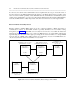
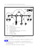
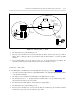
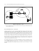
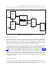


Table Of Contents
- Table of Contents
- ABOUT THIS DOCUMENT
- 1. INTRODUCTION TO CONNECTIVITY
- 2. COMMUNICATION SYSTEM NETWORKING (em AN OVERVIEW
- 3. TANDEM TIE TRUNK NETWORKS
- 4. MAIN-SATELLITE/TRIBUTARY (MS/T) NETWORKS THROUGH THE UDP OR MULTIPREMISES PACKAGES
- 5. ELECTRONIC TANDEM NETWORK (ETN) THROUGH THE ETN AND PNA PACKAGES
- 6. DISTRIBUTED COMMUNICATIONS SYSTEM (DCS)
- 7. DATA CONNECTIVITY - AN OVERVIEW
- 8. DATA COMMUNICATIONS CAPABILITIES
- 9. DATA COMMUNICATIONS CONFIGURATIONS
- A. RELATED DOCUMENTS
- B. SYNCHRONIZATION OF DIGITAL FACILITIES
- THE NEED FOR SYNCHRONIZATION
- SYNCHRONIZATION HIERARCHY
- CHANGES TO THE SCS SOFTWARE MADE AVAILABLE VIA SOFTWARE PATCHES
- NETWORK SYNCHRONIZATION AND ENGIINEERING
- AVAILABILITY OF SYNCHRONIZATION SOURCES
- CONCLUSIONS ON SYNCHRONIZATION
- USE OF GENERIC 2 AS A SYSTEM CLOCK REFERENCE
- USE OF GENERIC 1 AS A SYSTEM CLOCK REFERENCE
- C. TRUNKING TERMS AND CAPABILITIES
- D. COMMUNICATIONS PROTOCOLS
- E. LEAD DEFINITIONS
- F. NETWORKING FEATURES - AVAILABILITY MATRIX
- ABBREVIATIONS
- GLOSSARY
- INDEX
6-2 DISTRIBUTED COMMUNICATIONS SYSTEM (DCS)
_ ___________________________________________________________________________________________________________________________
_ ___________________________________________________________________________________________________________________________
_ ___________________________________________________________________________________________________________________________
DCS CLUSTERS
DCS is installed on groups of switches, called "DCS clusters." Nodes in DCS clusters can be DIMENSION,
System 75, System 85, Generic 1, or Generic 2 communications system. Each node must share the
cluster’s uniform numbering plan. That is, each extension in the network must be identified by the same
number of digits, and DCS users must reach each other by 4- or 5-digit extension-number dialing.
The number of nodes a DCS cluster can contain is dependent upon the type of switches in the cluster and
the version of switch software they are running. In addition, the number of nodes in a DCS cluster is
limited by the number of switches that can be connected to the node with lowest signaling link capacity and
the number of signaling links that are already used for other connections (such as connections with adjunct
processors). Shown below is a table giving the maximum number of DCS node connections each type of
switch can support.
Table 6-1. DCS Node Capacity
_ _____________________________________
Switch Node Capacity
_ _____________________________________
_ _____________________________________
DIMENSION 12
System 85, R2V1 12
System 85, R2V2 and V3 20
System 85, R2V4 63
Generic 2 63
System 75 64
Generic 1 64
_ _____________________________________
Figure 6-1 shows a DCS cluster. In the figure, a System 75 is connected to a System 85 DCS node through
both a tie trunk and a signaling link (PI/DCIU). While both System 85s are connected to a DIMENSION DCS
node by tie trunks and signaling links (DCIUs).
Note that a DCS network node can function as a DCS endpoint, or DCS tandem, or both. Network
endpoints are nodes that can initiate or terminate DCS calls; DCS tandem nodes relay interswitch DCS
calls. (See Engineering Considerations at the end of this chapter for a discussion of the number of hops for
which a DCS cluster should be engineered.) Note that the System 75 R1V2 and System 75 XE R1V2 can
function only as DCS endpoints.
DCS LINKS
As stated, DCS nodes communicate with each over two types of links: tie trunks and signaling links. The
tie trunks carry the actual voice communications, while the signaling links carry call information that the
destination switch uses to provide feature transparency.