
Instruction manual


CONFIGURATION GUIDELINES
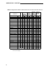
Extension Number—
enter the extension number.
● old—enter the old extension number to be replaced
● new—enter the new extension number
Bldg., Fir., Rm.— enter the identifying information for the location of the terminal or equipment.
Voice Terminal Type/Color—
enter the voice terminal information.
Voice Terminal Adjunct— enter adjunct equipment associated with the terminal, for example,
speakerphone, headsets, etc.
Module— enter MPDM, DTDM, MTDM, Z702AL1-DSU Data Module Base (Optional base for
7407D voice terminal), Z703AL1-DSU Data Module Base (Optional base for 7406D voice termi-
nal), 7400A, 7400B, 7500B, Call Coverage, Feature, or Display module, as applicable.
Power—
to be completed by the installation technician.
Blank—
use as necessary.
User name/use— enter the name of the user or the feature name as appropriate, for example,
SMDR.
Once the preceding information has been entered on the Port Assignment Record, enter the port
number on the System form you are completing. The port number consists of a network number
(1 = PPN cabinet, 2 = EPN cabinet 1, 3 = EPN Cabinet 2), the letter assigned the cabinet, and
four numbers that consist of the slot number (01 to 18) and the port number (01 to 08 or 01 to
24). A port number example for a single cabinet System (Control Cabinet only) with a circuit
pack mounted in slot 02 with port 08 assigned is A0208.
Step 3—Complete Circuit Pack Forms
(Account Team/Client)
Note: The Circuit Pack forms do not have to be completed if the System cabinet is
equipped with the circuit packs at the time of administration.
The Circuit Pack form allows the user to administer circuit packs to carrier slots before the circuit
packs are actually installed in the carrier or cabinet. This allows the System to be configured
(administered) when the circuit packs have not yet been physically inserted in the appropriate
slots. In order for any end-user equipment (voice terminals, data terminals, etc.) to be translated
into the System, either a circuit pack must be physically inserted in the appropriate slot or be logi-
cally installed using the circuit pack form.
The Circuit Pack forms are shown in Figure 9. The information entered on the form can be taken
from the Port Assignment Record.
24