
Instruction manual

CONFIGURATION GUIDELINES
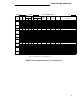
Module— enter MPDM, DTDM, MTDM, Z702AL1-DSU Data Module Base (Optional base
for 7407D voice terminal), Z703AL1-DSU Data Module Base (Optional base for 7406D
voice terminal), 7400A, 7400B, 7500B, Call Coverage, Feature, or Display module, as
applicable.
Power— to be completed by the installation technician.
Blank—
use as necessary.
User Name/Use— enter the name of the user or the feature name as appropriate, for
example, SMDR.
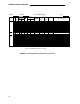
Once the preceding information has been entered on the Port Assignment Record, enter
the port number on the System form you are completing. The port number consists of a
network number (1 = PPN Cabinet, 2 = EPN Cabinet 1, 3 = EPN Cabinet 2), the letter
assigned the carrier, and four numbers that consist of the slot number (01 to 20) and the
port number (01 to 08 or 01 to 24). A0208 is a port number example for a single multi-
carrier cabinet System (no EPN Cabinet) and designates the Control Carrier with a circuit
pack mounted in slot 2 with port 08 assigned.
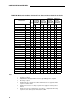
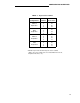
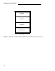
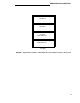
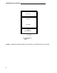
Single-Carrier Cabinet—Port Assignment Records:
Identify on Table C the cabinet type(s) and number of cabinets to be used in the system. Figures
6 through 8 show various single-carrier cabinet configurations. These are examples only and do
not depict all possible configurations. For example, some configurations may require fewer port
cabinets than are shown in the figures. Use the figures along with Table C to identify the type
cabinet (Control, Expansion, and Port) and number of each type cabinet in your System.
16