
Instruction manual


POWER AND GROUNDING
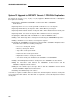
Single-Carrier Cabinet System
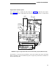
Each cabinet requires a separate DC power input. See Table AM for input DC power require-
ments. Figure 34 provides a typical DC powered and grounding arrangement for a single-carrier
cabinet system.
3 CONDUCTOR NO. 10
LINE CORD (ONE
PER CABINET)
TO CABINRT
C AND D
IF PROVIDED
GRD
PLATE (BETWEEN
EACH CABINET
RECEPTACLE
J58890CG DC
DISTRIBUTION
UNIT
6-AWG
WIRE
1-AWG
WIRE
-48V RTN
DISTRIBUTION
-48V
UNIT-NEXT
NETWORK
TO CONTROL CABINET
GRD BLOOK NEXT
NETWORK
DC POWER CABINET
75A
FIGURE 34. Typical Single-Carrier DC Power and Grounding Layout (EPN Colocated)
A ground wire is connected to the ground block of the bottom cabinet and routed to the battery
plant for termination on the Ground Discharge Bar. An approved ground must be terminated on
the Ground Discharge Bar.
171