
Instruction manual


POWER AND GROUNDING
EXPANSION PORT PROCESSOR PORT
NETWORK (EPN) CABINET
NETWORK (PPN) CABINET
FRONT
FRONT
DC POWER
DISTRIBUTION UNIT
-48 V
-48 V RTN
REAR
AC POWER
DISTRIBUTION
UNIT
REAR
AC
1-AWG UP
POWER
TO 50 FEET OR
CABINET
NEMA 5-50
CORD
ENGINEERED FOR
GROUND
OR
10 FEET
LESS THAN 1%
BLOCK
L6-30R
VOLTAGE DROP
RECEPTACLE,
OR
120-VOLT
EQUIVALENT
60-HZ 50-AMP
OR
208-VOLT
60-HZ 30-AMP
❍ ❍
(75A
SERVICE
GROUND
DISCHARGE
❍
BAR
-48V
❍
CUSTOMER
PROVIDED
APPROVED 10 AWG
POWER
GROUND COUPLED
PANEL
BATTERY PLANT
(SEE NOTE) BONDING
CONDUCTOR
NOTE.
(CBC)
AUXILIARY
6 AWG
CABINET
GROUND
CABINET
GROUND
TO
BLOCK
COUPLED
BONDING
CONDUCTOR
TO
APPROVED
6 AWG
GROUND
(SEE NOTE)
USE APPROVED GROUND LOCATED NEAREST THE
TELEPHONE COMPANY OWNED PROTECTOR GROUND BLOCK
AT THE BUILDING ENTRANCE FACILITY
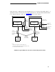
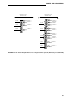
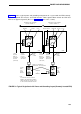
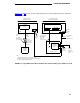
FIGURE 33. Typical Multicarrier Mixed AC/DC Power and Grounding Layout
(Remotely Located EPN)
For DC-powered systems, a ground wire must be installed from the isolated Ground Discharge
Bar on the battery plant to the Approved Ground. (See “Grounding.”) The size of the wire must
be no smaller than the largest wire in the system and must be larger than 6 AWG. The approved
ground connection must be identified with a Form 15657NR or equivalent grounding tag. The
Ground Discharge Bar shall not be connected electrically to the chassis of the chargers, power
board, or inverters. All output power must be isolated from the input power.
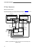
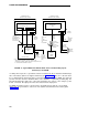
A 6-AWG ground wire must be connected to the ground block in the bottom of each cabinet
(Figure 34). The ground wire is routed out of the cabinet and terminated on the battery plant.
170