
Instruction manual


POWER AND GROUNDING
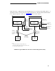
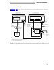
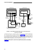
Figure 30 shows a typical power and grounding arrangement for a system with the EPN remotely
located. A ground wire must be connected from the cabinet ground block of both the PPN and
EPN to an approved ground. (Also see “Grounding,” later in this section).
EXPANSION PORT NETWORK PROCESSOR PORT NETWORK
CONTROL CABINET A CONTROL CABINET A
CIRCUIT POWER
15-AMP
BREAKER SUPPLY
PLUG
SINGLE-POINT
CIRCUIT POWER 15-AMP
GROUND BLOCK
BREAKER SUPPLY PLUG
OFF
OFF
OFF
OFF
ON
ON
ON ON
6 AWG
GROUND
WIRE TO
APPROVED
GROUND
(SEE NOTE)
REAR
10 AWG
POWER
6 AWG 10 AWG
POWER
COUPLED
CORD
GROUND
COUPLED
BONDING
CONDUCTOR
(SEE NOTE)
120-VOLT
60-HZ
15 OR
20 AMP
SERVICE
NOTE:
REAR
10 FEET
WIRE TO
BONDING
APPROVED
CONDUCTOR
GROUND (SEE NOTE)
(SEE NOTE)
NEMA 5-15 OR NEMA 5-20
RECEPTACLE, OR EQUIVALENT
MANAGER
I
TERMINAL
TO APPROVED GROUND LOCATED
NEAREST THE TELEPHONE COMPANY
OWNED PROTECTOR GROUND BLOCK
AT THE BUILDING ENTRANCE FACILlTY
CORD
10 FEET
120-VOLT
SO-HZ
15 OR
20 AMP
SERVICE
FIGURE 30. Typical Single-Carrier AC Power and Grounding Layout (Remotely Located EPN)
165