
Instruction manual


POWER AND GROUNDING
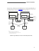
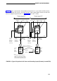
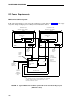
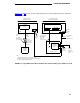
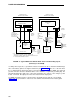
Figure 29 depicts a typical power and grounding layout for a single-carrier system with the PPN
and EPN cabinets colocated. A ground wire from the ground block on the bottom cabinet of the
EPN connects to the single-point ground block on the bottom cabinet of the PPN. A 6-AWG
ground wire connects the single-point ground block to an approved ground. (Also see “Ground-
ing,” later in this section).
EXPANSION PORT NETWORK
PROCESSOR PORT NETWORK
CONTROL CABINET A
CONTROL CABINET A
CIRCUIT
POWER
15-AMP
BREAKER
SUPPLY
PLUG
OFF OFF
OFF OFF
ON ON
ON
ON
6 AWG
REAR
120-VOLT
60-HZ
15 OR
20 AMP
SERVICE
NOTE:
SINGLE-POINT
CIRCUIT
POWER
15-AMP
GROUND BLOCK
BREAKER
SUPPLY
PLUG
10 AWG
POWER
COUPLED
BONDING
CONDUCTOR
(SEE NOTE)
10 FEET
6 AWG
NEMA 5-15 OR
NEMA 5-20
RECEPTACLE,
OR EQUIVALENT
REAR
10 AWG
POWER
COUPLED
CORD
BONDING
10 FEET
GROUND
CONDUCTOR
WIRE TO
(SEE NOTE)
APPROVED
GROUND
(SEE NOTE)
MANAGER
I
TERMINAL
120-VOLT
60-HZ
15 OR
20 AMP
SERVICE
TO APPROVED GROUND LOCATED NEAREST THE TELEPHONE COMPANY OWNED
PROTECTOR GROUND BLOCK AT THE BUILDING ENTRANCE FACILITY
FIGURE 29. Typical Single-Carrier Power and Grounding Layout (EPN Colocated)
164