
Instruction manual


POWER AND GROUNDING
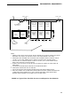
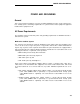
Figure 25 depicts a typical power and grounding layout for colocated PPN and EPN cabinets. A
ground wire from the ground block on the EPN cabinet connects to the single-point ground block
on the PPN cabinet. A 6-AWG ground wire connects the single-point ground block on the PPN
cabinet to an approved ground. (Also see “Grounding,” later in this section).
Note that the AC powering for a multicarrier cabinet
EXPANSION PORT
NETWORK CABINET
is as shown in Figure 15 for the PPN cabinet.
PROCESSOR PORT
NETWORK CABINET
FRONT
FRONT
6 AWG
SINGLE-POINT
GROUND BLOCK
POWER
DISTRIBUTION
UNIT
POWER
DISTRIBUTION
UNIT
6 AWG
TO AUXILIARY
CABINET
GROUND BLOCK
REAR
POWER CORD COUPLED
POWER
10 FEET
NEMA 5-50
BONDING
CORD
10 AWG
TO APPROVED
OR
CONDUCTOR
10 FEET
6 AWG
GROUND
L6-30R 10 AWG
10 AWG
(SEE NOTE)
RECEPTACLE,
OR EQUIVALENT
120-VOLT
60-HZ 50-AMP
CUSTOMER
60-HZ 50-AMP
OR
PROVIDED
OR
208-VOLT
POWER
208-VOLT
60-HZ 30-AMP
PANEL
60-HZ 30-AMP
SERVICE
SERVICE
COUPLED
BONDING
CONDUCTOR
NOTE:
USE APPROVED GROUND LOCATED NEAREST THE
TELEPHONE COMPANY OWNED PROTECTOR GROUND BLOCK
AT THE BUILDING ENTRANCE FACILITY
FIGURE 25. Typical Multicarrier System AC Power and Grounding (EPN Colocated)
160