
Instruction manual


HARDWARE AND SOFTWARE DETERMINATION
a.
b.
●
●
●
Assume USA DTMF standards for each call type:
● 11-digit outgoing -10.15 seconds
● 8-digit outgoing - 8.2 seconds
● External operator assisted -14.3 seconds
● 16-digit international - 33.4 seconds
or, to time the total time between starting dialing and ringing from the far end for
one of each call type on a similar switch already connected to the same network
using a stop watch.
Determine the number of digits to be dialed. Include the equivalent of 1 extra
digit for the group II signal.
Multiply that by the seconds required to send each digit. The time may vary
between 0.17 and 0.3 seconds per digit, depending on the CO. Assume 0.3
seconds per digit if the answer is not known.
Add to that time for detecting end of dial. This may happen within the switch or
by receiving a group B signal from the far end. Choose whichever of the follow-
ing that applies to the type of call you are considering. If more than one applies,
choose the longest time:
10 secs.
ARS not used
10 secs.
Number matches 1 ARS digit string
3 secs.
Number matches 2 or more ARS strings
The administered time of the
forward signal absent timer.
The administered time of the
forward signal present timer or
the typical call setup time within
the national or private network.
Call setup time within the net-
work can vary greatly depending
on the type of call and the coun-
try. Contact the local PTT for
their typical call setup times.
2.
3.
Multiply the time for each call type by the expected number of outgoing calls of each type
in the busy hour, divided by 100. The result is called the CCS, which stands for hundred
call seconds.
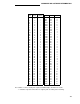
Use the CCS and the tables above to determine the number of service circuit ports
required.
126