
Instruction manual


HARDWARE AND SOFTWARE DETERMINATION
Circuit Pack Determination
Terminals, trunks, auxiliary equipment, and customer-provided equipment (CPE) require an inter-
face (circuit pack) to be connected to the system.
Note: All circuit packs in this section are referred to by their circuit pack numbers only.
Version letters (for example, the “B” in TN750B, the “C” in TN464C) are not
included. Assume the latest version is to be used for all circuit packs unless other-
wise specified.
Any customer-provided equipment that is not FCC-registered requires a 36A Coupler (for music)
or 278A adapter (for paging) and a 2012D Transformer. This enables a customer to connect an
external music or paging system to the switch where the interface may not match exactly.
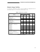
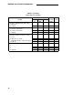
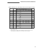
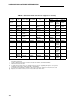
Determine the types and quantities of circuit packs on the following worksheets, and enter the
totals in Table Q. Note especially that circuit pack selection may differ depending on the country
in which the system is to be installed. Different country’s having different signaling and tone
requirements. Tables are provided below, before the worksheets, to help you determine which
circuit packs are appropriate for the country in question. Information required in these
worksheets may be obtained from the tables previously filled out in this manual and from the
tables of circuit packs per country. For a detailed description of the system’s circuit packs, see
DEFINITY Communications System Generic 3 System Description, 555-230-200.
For a G3i or G3i-Global, two memory circuit packs are required for simplex systems and four for
duplex systems (PEC 63526). For a G3r, the quantity is predetermined at two memory circuit
packs, so no planning is required.
For G3i CallVisor® ASAl, one packet control circuit pack (PEC 63533) and one ISDN-BRI circuit
pack (PEC 65512) are required for a simplex system. If G3i is duplicated with CallVisor ASAI,
two packet control circuit packs plus one TN771 Maintenance circuit pack (PEC 65524) per port
network are required.
For G3r CallVisor ASAl, the packet control circuit pack(s) and, for duplicated systems, mainte-
nance circuit pack are already included in the configuration, so the only circuit pack required from
planning is one ISDN-BRI circuit pack (PEC 65512).
In G1, G3i, and G3i-Global configurations, port networks are connected directly to each other. In
G3r, where there are four or more port networks, they are connected to the TN573 Switch Node
Interface circuit pack, with one TN573 for each port network. The TN573 circuit packs are located
in a switch node carrier, usually the PPN, E Carrier. This configuration, called the Center Stage
Switch (CSS), reduces the amount of connections needed between port networks. You can have
a CSS for fewer than four port networks, but it is not recommended unless you anticipate
expanding to four or more port networks.
Each G3r cabinet, including the PPN that contains the CSS, requires an Expansion Interface
TN570. Only the CSS in the PPN contains a Switch Node Interface TN573 and Switch Node
Clock TN572. If one of the cabinets is remoted, both ends of the connection require a DS1 Con-
verter TN574. The TN776 Expansion Interface circuit pack cannot be used for the G3r CSS.
Note also that the TN776 Expansion Interface circuit pack is required with ISDN-BRI in the G3i or
G3i-Global, but cannot be used at all in the G3r. The Expansion Interface circuit pack for the G3r
is the TN570.
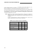
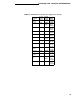
Table Q shows the capabilities of the different Speech Synthesis circuit packs. The TN457
103