
User guide

Initial System Administration
3-18 Issue 1 September 1995
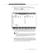
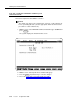
The Logical Channel, Switch Port, and AUDIX numbers must be the same
as the corresponding numbers administered on the switch. These fields
have different names on the switch screens. The field names on the switch
screens corresponding to the DEFINITY AUDIX Switch Link screen field
names are shown in the following table:
3. If the DEFINITY AUDIX System is operating in a DCS environment, repeat
step 3 for each remote switch-node in the DCS network. Refer to
Worksheets B-9 through B-15.
NOTE:
DCS-related switch administration must be done in conjunction with
this task for each switch in the the DCS network.
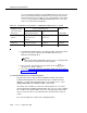
4. Once you have entered values for these fields, press the (F3)
function key to save the changes.
5. Proceed to ‘‘Task 14F: Synchronize DEFINITY AUDIX System and Switch
Clocks’’ on page 3-20.
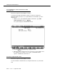
Set Switch-Link Parameters for DS Integration
This part of the task is required only if the DEFINITY AUDIX system will be
running in DS integration mode. Check Worksheet C-1:
Activate Customer
Options
, to see if the switch integration type is to be display-set. If so, enter
change switch-link at the DEFINITY AUDIX command line.
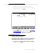
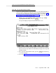
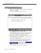
If the switch to be installed does indeed use DS Integration, the screen that
appears will be labeled
Switch Link Embedded
. This screen is used to establish
two conditions: first, which AUDIX system is to be integrated into which switch,
and second, how a call is to be treated when the call answer timeout period
expires.
The screen that appears resembles the following illustration:
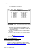
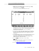
Table 3-2. Field-Name Correspondence — DEFINITY AUDIX System vs. Switch
DEFINITY AUDIX Processor Channel Screen
Remote
Switch-link DCIU-
SCI Screen System 75, G1, G3i,s,vs G3r System 85/G2
AUDIX Port Logical
Channel
Interface Channel, or
Remote Processor
Channel
Interface Channel, or
Remote port
Remote port
Switch Port Processor Channel Local Port Local Port
AUDIX Machine ID Machine ID Machine ID
ENTER