
User guide

Task 8: Install the Control-Link Cable
Issue 1 September 1995
2-27
Connect to the TN577 via DSUs (G3r Only)
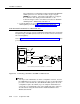
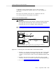
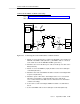
Refer to Figure 2-15, Connecting the Control Link Cable to a TN577 via DSUs,
when performing this task.
Figure 2-15. Connecting the Control Link Cable to a TN577 via DSUs
1. Attach one end of the Group 311 cable to the RS-232C connector labeled
PORT B on the MFB Y-cable (labeled 1). (The MFB Y-cable is connected
to the fourth slot of the five DEFINITY AUDIX system slots.)
2. Attach the other end of the Group 311 cable to the Group 110 cable of the
DSU (labeled 2).
3. Attach one end of the D8W-87 (4-pair) modular cord to the modular jack
on the DSU (labeled 3).
4. Attach the other end of the D8W-87 modular cord to the 103A adapter with
a 3-pair cord (labeled 4).
5. Attach the 3-pair cord from the 103A adapter to the cross-connect field
(labeled 5). (Remember to swap transmit and receive pairs at the
cross-connect field. See the DSU reference manual for more information
on DSU connectivity.)
6. Connect the second 103A adaptor, D8W-87 modular cord, and DSU as
before.
7. Connect the M25A cable to the modular jack on the DSU (labeled 6).
H600-353, Grp 2
ALB
CABLE
6
5
4
3
SWITCH
DEFINITY AUDIX
ALARM
BOARD
DEFINITY AUDIX
MULTI-
FUNCTION
BOARD
MFB
Y
CABLE
21
PORT
B
Grp
311
PORT
A
110 V
DSU
103A103A
3
PAIR
3
PAIR
H600-352,
Grp 1
RS-232C
M25A
X-C
DSU
110 V
D8W-87
D8W-87
G3r ONLY
TN577
PACKET
GATEWAY
7
8
(USE ONE
RS-232C
CONNECTOR)
H600-347,
Grp 1