
User guide

Hardware Installation
2-26 Issue 1 September 1995
Connect to the Packet Gateway Board (G3r only)
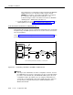
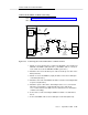
Refer to Figure 2-14, Connecting the CL Cable to a Packet Gateway Board (G3r
Only), when performing this task.
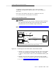
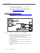
Figure 2-14. Connecting the CL Cable to a Packet Gateway Board (G3r Only)
1. Attach one end of the H600-405 cable to the RS-232C connector labeled
PORT B on the MFB Y-cable (labeled 1). (The MFB Y-cable is connected
to the fourth slot of the five DEFINITY AUDIX system slots.)
2. Attach the other end of the H600-405 cable to the
out
RS-449 connector of
the IDI (labeled 2).
3. Attach the one of the four RS-232 connectors on the H600-347 cable to
the
in
RS-449 connector of the IDI (labeled 3).
4. Attach the other end of the H600-347 cable to an RS-232C connector on
the Packet Gateway board (TN577) on the G3r switch (labeled 4).
5. Proceed to Task 9: Install the Printer (Optional).
H600-353, Grp 2
MFB
Y
CABLE
ALB
CABLE
DEFINITY AUDIX
ALARM
BOARD
DEFINITY AUDIX
MULTI-
FUNCTION
BOARD
SWITCH
PORT A
PORT B
H600-352,
Grp 1
3
H600-347, Grp 1
(USE ONE RS-232
CONNECTOR)
H600-210,
Grp n
H600-405, Grp 1
IN OUT
2
1
G3r ONLY
TN577
PACKET
GATEWAY
IDI
4