
User guide

Task 8: Install the Control-Link Cable
Issue 1 September 1995
2-25
Connect to the Digital Line Interface (TN754)
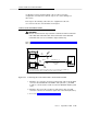
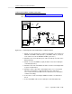
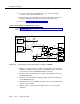
Refer to Figure 2-13, Connecting the Control Link Cable to a Digital-Line
Interface, when performing this task.
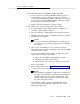
Figure 2-13. Connecting the Control Link Cable to a Digital-Line Interface
1. Attach one end of the (ED1E-434-11) Group 311 cable to the RS-232C
connector labeled PORT B on the MFB Y-cable (labeled 1). (The MFB
Y-cable is connected to the fourth slot of the five DEFINITY AUDIX system
slots.)
2. Attach the other end of the Group 311 cable to the RS-232C connector of
the MPDM (labeled 2).
3. Attach one end of the D8W-87 (4-pair) modular cord to the modular jack
on the MPDM (labeled 3).
4. Attach the other end of the D8W-87 modular cord to the 103A adapter
modular jack (labeled 4).
5. Attach a 3-pair cord from the 103A adapter to the cross-connect field
(labeled 5).
6. Attach a 25-pair cable between the cross-connect field and the digital line
interface board (TN754) on the switch (labeled 6).
7. Proceed to Task 9: Install the Printer (Optional).
H600-353, Grp 2
ALB
CABLE
GROUP 311
CABLE
1
DEFINITY AUDIX
MULTI-
FUNCTION
BOARD
DEFINITY AUDIX
ALARM
BOARD
SWITCH
PORT B
PORT A
H600-352,
Grp 1
MFB
Y
CABLE
103A
2
3
4
MPDM
5
X-C
3 PAIR
6
25 PAIR I/O
TN754
All Switches
Except G3r
PI/TN765
110 V
D8W-87