
User guide

Hardware Installation
2-24 Issue 1 September 1995
Connect to the PI with an IDI
Refer to Figure 2-12, Connecting the Control Link Cable to the PI with an IDI,
when performing this task.
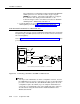
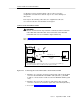
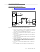
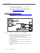
Figure 2-12. Connecting the Control Link Cable to the PI with an IDI
1. Attach one end of the H600-405 cable to the RS-232C connector labeled
PORT B on the MFB Y-cable (labeled 1). (The MFB Y-cable is connected
to the fourth slot of the five DEFINITY AUDIX system slots.)
2. Attach the other end of the H600-405 cable to the
out
RS-449 connector of
the IDI (labeled 2).
3. Attach the RS-449 end of the H600-210 cable to the
in
RS-449 connector
of the IDI (labeled 3).
4. Attach the RS-232C end of the H600-210 cable to an EIA connector on the
Processor Interface (PI) (labeled 4).
5. Proceed to Task 9: Install the Printer (Optional).
H600-353, Grp 2
H600-352
Grp 1
MFB
Y
CABLE
ALB
CABLE
SWITCH
DEFINITY AUDIX
ALARM
BOARD
DEFINITY AUDIX
MULTI-
FUNCTION
BOARD
PORT A
PORT B
and switches using the EIA connector on the PI board for another adjunct (such as CMS).
* Other excluded switches are: duplicated G3i, switches on DC power, System 75 R1V3 without a PI/EIA port,
H600-405, Grp 1
IN OUT
2
1
PI / EIA
PI / TN765
Most Switches*
Except G3r
IDI
4
3
H600-210, Grp n