
User guide

Task 8: Install the Control-Link Cable
Issue 1 September 1995
2-23
Use Worksheet A-4 to determine which of the six cable-connection
configurations to install. Then follow the steps in one of the following four
subsections.
In the steps in the following subsections, the equipment described is
cross-referenced to the circled numbers in the figures.
Connect to the PI without an IDI
!
WARNING:
Electric shock and/or fire may result from a cabinet-to-cabinet connection
of the H600-406 control-link cable. Direct connection of the H600-406
control-link cable is to be used within a single cabinet only.
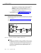
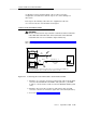
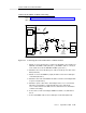
Refer to Figure 2-11, Connecting the Control Link Cable to the PI without an IDI,
when performing this task.
Figure 2-11. Connecting the Control Link Cable to the PI without an IDI
1. Attach the one end of the synchronous null modem cable to the RS-232C
connector labeled PORT B on the MFB Y-cable (labeled 1). (The MFB
Y-cable is connected to the fourth slot of the five DEFINITY AUDIX system
slots.)
2. Attach the other end of the synchronous null modem cable to an EIA
connector of the Processor Interface (PI) board on the switch (labeled 2).
3. Proceed to Task 9: Install the Printer (Optional).
H600-353, Grp 2
ALB
CABLE
1
H600-406, Grp 1 or 2
SYNCHRONOUS
NULL MODEM
CABLE
PORT A
PORT B
DEFINITY AUDIX
MULTI-
FUNCTION
BOARD
SWITCH
DEFINITY AUDIX
ALARM
BOARD
MFB
Y
CABLE
2
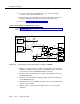
PI / EIA
PI / TN765
Most Switches*
Except G3r
H600-352
Grp 1
and switches using the EIA connector on the PI board for another adjunct (such as CMS).
* Other excluded switches are: duplicated G3i, switches on DC power, System 75 R1V3 without a PI/EIA port,