
User guide

Hardware Installation
2-22 Issue 1 September 1995
h. Set the terminal options. Refer to Appendix B, ‘‘Option Settings’’, for
a complete list of option settings for all supported terminals.
NOTE:
When installing a serial printer on all but a 610 or 615 BCT, set
the options on the printer as described in the manual supplied
with the printer, then set the corresponding options on the
terminal to match. On the 610/615, set the terminal options
first, then set the printer options.
i. At the terminal, enter AT.
If the 7400B data set is connected correctly, it responds with “OK”
(on the terminal screen).
j. Enter ATDT and the phone number of the 7400A data set
connected to the DEFINITY AUDIX system (refer to the
Terminals
worksheet for this number).
After a connect interval, if the terminal and 7400 data sets are
installed correctly (and the DEFINITY AUDIX system is in either
ADX
,
OAM
,
OS
or
AINIT
state), the screen displays the login
prompt.
If login prompt is not displayed when the DEFINITY AUDIX system
is in one of the above states, try pressing the key a few
times. If the login prompt still does not appear, write down the state
displayed on the LCD then see the troubleshooting procedures for
terminal connections in
DEFINITY AUDIX System — Maintenance
,
585-300-110.
4. For CL integration, proceed to Task 8: Install the Control-Link Cable. For
DS integration, proceed to Task 9: Install the Printer (Optional).
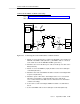
Task 8: Install the Control-Link Cable
This task is required only if the DEFINITY AUDIX system is to be run in the CL
integration mode.
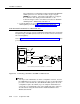
The control-link cable can be connected to the switch in one of the following six
ways:
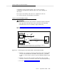
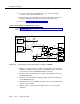
■ Directly to the processor interface (PI) board
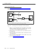
■ Via an IDI to the processor interface (PI) board (TN765)
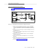
■ Via an MPDM to the digital-line interface board (TN754)
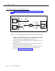
■ Via an IDI to the packet gateway board (TN577) of a G3r only
■ Via DSUs to the packet gateway board (TN577) of a G3r only
■ Via MPDMs to the packet gateway board (TN577) of a G3r only
RETURN