
User guide

Hardware Installation
2-16 Issue 1 September 1995
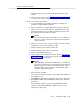
Task 7B: Install a Terminal via Modems
This task describes how to connect a terminal via a modem to Port B (DP
integtration only) of the MFB. (This task can also be used for remote connection
to Port A, whether DS or CL integration.)
To make sure the modems that you are installing are on the list of supported
peripherals, refer to
DEFINITY AUDIX System — System Description,
585-300-205.
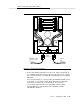
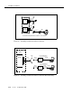
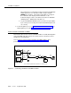
Refer to Figure 2-8, Connecting a Terminal to the MFB via a Modem, when
performing this task.
Figure 2-8. Connecting a Terminal to the MFB via a Modem
1. In the room where the switch and DEFINITY AUDIX system are located,
place one modem between the DEFINITY AUDIX system and a telephone
jack, close enough to each that the cables can easily reach. Also make
sure the modem is within reach of a power outlet.
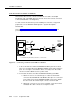
2. Connect the modem to Port B of the DEFINITY AUDIX system MFB.
a. Attach one end of one of the Group 311 cables to the RS-232
connector labeled PORT B on the MFB Y-cable (the one connected
to the fourth slot of the five DEFINITY AUDIX system slots). Attach
the other end to the female 25-pin connector on the modem.
b. Attach the connector on one end of a modular cord to the modem,
and attach the other connector to a telephone outlet.
RS232PORT B
PORT A
MFB
Y
CABLE
ALB
CABLE
ALARM
BOARD
SWITCH
MULTI-
FUNCTION
BOARD
MODEM MODEM
GROUP 311 CABLE
TIP/
RING
NOTE
*SEE
DIAL-UP
TERMINAL
OPTIONAL
PRINTER
*NULL MODEM IS REQUIRED WHEN CONNECTING TO 715 BCT DCE PORT.