
User guide


Hardware Installation
2-8 Issue 1 September 1995
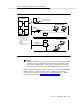
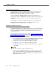
The following list describes the positions of the LCD.
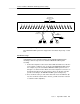
■ Standing to the right of the faceplate and reading from bottom to
top, the first position contains the DEFINITY AUDIX system
heartbeat.
■ The second and third positions display two letters indicating the
following types of alarms: warnings (WN), minor (MN) and major
(MJ). These positions are blank if there are no alarms.
■ The remaining positions indicate the DEFINITY AUDIX system
states or menu selections.
See
DEFINITY AUDIX System — Maintenance,
585-300-110 for a
complete description of the LCD display.
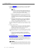
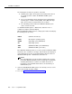
When the DEFINITY AUDIX system is coming up, the LCD should display
the following states (in order):
If the DEFINITY AUDIX system does not come up to the AUDIX state within
30 minutes (10 to 15 minutes is average), write down the state displayed
on the LCD, then refer to the associated troubleshooting procedures in
DEFINITY AUDIX System — Maintenance
, 585-300-110.
NOTE:
If the red LED at the top of the faceplate is flashing after you have
inserted the DEFINITY AUDIX system assembly, ignore it at this time.
A flashing LED indicates a software error which, at this time, is
probably a port board alarm that should resolve itself when you
administer the ports.
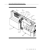
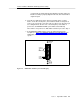
8. Unless the fifth DEFINITY AUDIX system slot is already covered, cover it
with a 1/2-inch blank faceplate adapter.
9. Proceed to Task 6: Connect the Alarm Board Cable.
BTEST (Firmware board tests)
BOOT (Booting the operating system)
OSINIT (Operating system initialization)
OS (Operating system)
AINIT (DEFINITY AUDIX system initialization)
ADX (DEFINITY AUDIX system state)