
User guide


Task 5: Install the DEFINITY AUDIX System Assembly
Issue 1 September 1995
2-7
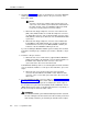
or reinsert the assembly after the first attempt to insert it; make sure
that the assembly is properly aligned in the slot, then insert it with a
single firm push.
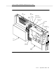
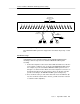
6. Insert the assembly and lock it in place by pushing up the securing
latches on the two circuit packs. (It is normal for the two circuit packs to
feel loosely connected to each other. This is to allow some give when you
are seating them into the two slots of the backplane.) If the switch is
powered on, the DEFINITY AUDIX system will boot automatically.
If the switch is not powered on, wait until it is and then proceed to Step 7.
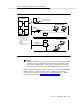
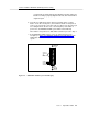
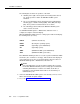
7. As the DEFINITY AUDIX system comes up, watch the LCD on the
faceplate (see Figure 2-3, DEFINITY AUDIX System LCD Display). The
LCD display identifies the states and alarms for the DEFINITY AUDIX
system.
Figure 2-3. DEFINITY AUDIX System LCD Display
STATE OF
OPERATION
OR
MENU
SELECTION
ENTER/YES
BUTTON
FLASHING
HEARTBEAT
BACK
BUTTON
ALARM
NEXT/NO
BUTTON