
User guide


Hardware Installation
2-6 Issue 1 September 1995
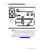
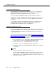
3. Referring to Figure 2-1 and Steps 3a and 3b below, connect the DEFINITY
AUDIX system assembly adaptor cables to the port connectors on the
back of the switch.
NOTE:
You must connect these adaptor cables directly to the port
connectors on the switch. If you install another cable between
the switch and the cables, the DEFINITY AUDIX system will
not operate correctly (either now or in the future).
a. Attach the male D-type amphenol connector on the alarm board
(ALB) cable (H600-353-G2, the one with two amphenol connectors,
one RJ45 LAN connector, and one 25-pin RS-232 connector) to the
ALB (TN2169 or TN2170), the third slot of the five DEFINITY AUDIX
system slots.
b. Attach the male D-type amphenol connector on the multifunction
board (MFB) Y-cable (H600-353-G2, the one with one amphenol
and two RS-232 connectors) to the MFB (TN566B or TN567), the
fourth slot of the five DEFINITY AUDIX system slots.
If you are installing the DEFINITY AUDIX system in a DC-powered switch,
perform the following steps to install the opto-isolators. Otherwise, skip to
Step 5.
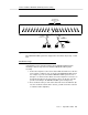
4. Install the 116A opto-isolators.
a. Attach the male end of a null modem (supplied with the DEFINITY
AUDIX system PEC) to the RS-232C connector labeled PORT A on
the MFB Y-cable. Attach the male connector of the 116A
opto-isolator to the other end of the null modem.
If the DEFINITY AUDIX system is to use DS integration
and
if two terminals
are to be installed, install the second opto-isolator. Otherwise, proceed to
Step 5.
b. Attach the male end of another null modem to the RS-232C
connector labeled
PORT B
on the MFB Y-cable. Attach the male
connector of the second 116A opto-isolator to the other end of the
null modem.
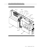
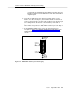
5. Insert the DEFINITY AUDIX system assembly (see Figure 2-1, DEFINITY
AUDIX System Assembly) into the switch cabinet as follows:
Holding the DEFINITY AUDIX system assembly by the outside edges of
the faceplate, line up the alarm board (ALB) and the multifunction board
(MFB) with the bottom guides of the third and fourth slots, respectively, of
the five reserved port slots in the switch carrier.
!
WARNING:
The DEFINITY AUDIX system will automatically boot when seated in
the slots. Damage to the disk could occur if the assembly is removed
while booting. Therefore, you should try to avoid the need to adjust