
User guide

Task 5: Install the DEFINITY AUDIX System Assembly
Issue 1 September 1995
2-5
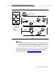
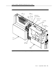
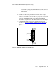
Figure 2-2. Connecting the Adaptor Cables Rear-Panel View
If the DEFINITY AUDIX system was shipped in a new switch, skip to Step 7 of this
task.
Installation Steps
Using Worksheet A-3,
Port Slot Locations for the DEFINITY AUDIX System
Assembly
, follow the steps below to install the DEFINITY AUDIX system
assembly.
1. Remove the amphenol connectors from the third and fourth slots of the five
(four for G3vs) contiguous slots reserved for the DEFINITY AUDIX system.
For example, if you are to install the DEFINITY AUDIX system in slots 7
through 11 of carrier A in the switch, remove the amphenol connectors on
the Group 300 cables from slots 9 and 10. (These are the two slots that
provide connectivity to the DEFINITY AUDIX system circuit packs.)
2. Dress down the cable you removed from the 4th slot to the wall field. (Do
not dress down the cable from the 3rd slot, you will use it in the next task
to cable the alarm origination.)
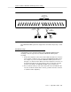
MFB
Y-CABLE
(H600-352-G1)
1 2 3 4 5 6 7 8 9 1011 12 13 14 15 16 17 18 19 20
AMPHENOL
CONNECTOR
ALB
CABLE
(H600-353 G2)
FEMALE
RJ45
FEMALE
RS-232
FEMALE
RS-232
FEMALE
RS-232
1st 2nd 3rd 4th 5th
EXAMPLE OF
DEFINITY AUDIX
SLOTS