
User guide


Task 4: Verify the Components and Connectivity
Issue 1 September 1995
1-5
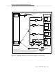
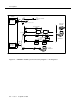
Figure 1-1. DEFINITY AUDIX System Connectivity Diagram — CL Integration
TN765
Processor
Interface
Most Switches†
Except G3r
All Switches
Except G3r
TN754
Digital Line
Interface
TN765
Processor
Interface
G3r ONLY
IDI
IDI
SYNCHRONOUS NULL
MODEM CABLE
* Administered Connection
† Other excluded switches are: duplicated G3i, switches on DC power, System 75 R1V3 without a
PI/EIA port, and switches using the EIA connector on the PI board for another adjunct (such as CMS).
‡ If ADAP software is used on this terminal, the administrator must have dial-up capabilities.
The terminal must therefore be connected to PORT A via a modem connection.
PORT B
PORT A
RS-232 TO NON-US MODEM
TO
CROSS-CONNECT
FIELD (X-C)
LAN
ALB
CABLE
MPDM
MPDM
DSUDSU X-C
X-C
X-C
MPDM X-C
110 V
110 V
110 V110 V
110 V
MFB
Y
CABLE
SWITCH
ALARM
BOARD
MULTI-
FUNCTION
BOARD
LOCAL
TERMINAL‡
TN577
Packet
Gateway
TN754
*
TN754
Digital Line
Interface