
User guide
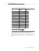

Option Settings
B-14 Issue 1 September 1995
Jumper Setting
A jumper switch is located inside the front endcap of the modem. The jumper
must be set to the command mode when setting the options listed in the previous
section. After setting the options, the jumper must be set to the noncommand
mode for normal operation with the DEFINITY AUDIX System.
To access the jumper switch, the front endcap of the modem must be removed.
First turn off the modem and disconnect it from the power source, the telephone
line, and the computer.
!
CAUTION:
Before removing the modem’s endcap, always unplug the telephone line
and turn off power to the modem. If a telephone is plugged into the
PHONE
jack on the modem’s rear panel, remove it. Do not operate the modem
without the endcaps or housing in place. Doing so may expose electrically
live parts and create a safety hazard.
To remove the front endcap, first insert a screwdriver under the front-endcap tab
located on the side of the modem. Twist the screwdriver slightly to loosen the tab
and then remove the endcap.
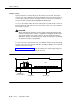
Figure B-1, Modem Front View, shows the jumper pins and the jumper plug in a
front view of the modem with the endcap removed.
Figure B-1. Modem Front View
CIRCUIT BOARD JUMPER PINS
JUMPER PLUG
(IN DUMB POSITION)
LEDs
JP1