1/16/92 AT&T AT&T Door Phone Controller Installation and Operation Manual
© 1992, AT&T All Rights Reserved Printed in U.S.A. CIC# 999-500-315 0II722050-055 Issue 3, November 1992 NOTICE Every effort was made to ensure that the information in this manual was complete and accurate at the time of printing. However, information is subject to change. COMPATIBILITY The AT&T Door Phone Controller is recommended for use with any AT&T business telephone system. It is also intended to be used with the AT&T Door Phone Speaker.
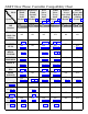
AT&T Door Phone Controller Compatibility Chart Mode System Dedicated Trunk Loop Start (Section 4) Dedicated Trunk Ground Start (Section 4) Station Trunk Port Access Saver Saver Aux.
Application Notes (for Compatibility Chart) iv 1. When used in any mode of a System 25, if the user initiates a call to the door and he wishes to enter the Option Selection mode, pressing three pound keys followed by the digit 3 (i.e., # # # 3, not # # 3) must be entered. Actually, the first # does not seem to be recognized at any time during the call. However, it should be noted that only # # 3 is needed to enter the Option Selection mode when the call is initiated from the door button press. 2.
Application Notes (for Compatibility Chart) continued 9. Tip/Ring telephone sets connected to the Merlin System through a BTMI cannot use Port Saver/ Trunk Saver operation. The BTMI wiII not transmit the required hook-flash signal. 10. System 75 requires a pound (#) to be dialed at the end of every dial string. This is required to send the dialed number to the trunk port. 11. Tip/Ring telephone sets cannot be used in this mode to access the AT&T Door Phone. 12.
Contents 1 2 Introduction 1-1 ■ Using This Manual ■ Features ■ Terms You Should Know 1-2 1-3 1-5 Installation Procedures 2-1 ■ ■ ■ ■ ■ ■ ■ ■ ■ ■ ■ 3 Important Safety Information General Information Introduction Door Phone Controller Back Panel Connections Prior to Installation AT&T Door Phone Controller Location Installation Connecting Door Speaker, Door Button, and Door Ajar Switch to the AT&T Door Phone Controller Connecting Power Operation and Controls Information Connecting the AT&T Door Pho
4 Installation for Telephone Systems With Available Dedicated Trunk Port 4-1 ■ Overview ■ DIP Switch Selections 4-2 4-2 4-3 4-6 4-8 ■ Installation ■ Option Selection ■ Operation – Basic Door Answer Function 5 Installation for Telephone Systems With Available Station Port 5-1 ■ 5-2 5-2 5-3 5-5 5-8 ■ ■ ■ ■ 6 Installation for Telephone Systems Without Available Dedicated Trunk or Station Port 6-1 ■ 6-2 6-2 6-3 6-5 6-6 6-9 ■ ■ ■ ■ ■ 7 Overview DIP Switch Selections Installation Option Select
A DIP Switch Settings B Option Selection Mode Definitions B-1 C Specifications C-1 D Using the AT&T Door Phone Controller With an Answering Machine D-1 E AT&T Auxiliary Alert Option E-1 F FCC Regulations and Warranty F-1 A-1 ix
Figures 1 2 Introduction 1-1 1-1. 1-4 Installation Procedures 2-1. 2-2. 2-3. 2-4. 2-5. 2-6. 2-7. 2-8. 2-9.
4 Installation-Dedicated Trunk Port 4-1 4-1. 4-3 4-2a. 4-2b. 5 Installation-Dedicated Station Port 5-1. 5-2. 6 DIP Switch Setting for PBX With Shared Trunk Port Connecting The AT&T Door Phone Controller to a Telephone System With Shared Trunk Port Using the Door Phone Controller With An Answering Machine D-1. D-2.
Tables 3 Installation-Home/Residential 3-1. 4 Installation-Dedicated Trunk Port 4-1. 5 xii AT&T Door Phone Controller Option Selection Information Installation-No Dedicated Trunk/Station Port 6-1. 7 AT&T Door Phone Controller Option Selection Information Installation-Dedicated Station Port 5-1. 6 AT&T Door Phone Controller Option Selection Information AT&T Door Phone Controller Option Selection Information 3-1 3-6 4-1 4-8 5-1 5-7 6-1 6-8 Troubleshooting and Maintenance 7-1 7-1.
Introduction 1 Introduction 1-1
Using This Manual This manual will help you install, program and operate the AT&T Door Phone Controller. It contains important information on what features are available and how to use them. We urge you to read this manual prior to installing the AT&T Door Phone Controller; this will ensure that you are using the product to its fullest capability. Section 1 (this section) provides basic information on what the AT&T Door Phone Controller is and what are its features.
The AT&T Door Phone Controller The AT&T Door Phone Controller provides multi-functional control for communications to a dedicated door-speaker unit and a remote door-unlocking device. The AT&T Door Phone Controller (see Figure 1-1) can be used alone, or it can be used along with a PBX (Private Branch Exchange) or communications system to alert personnel within a residence or building that someone is requesting attention at the entrance.
SPEAKER VOLUME TALK BACK VOLUME DIP SWITCH LED Figure 1-1.
Terms You Should Know AuxiliaryAlert —A door speaker’s push button can activate a bell/chime within the building. Cadence —Telephone Ringing cycle, i.e., 2 second ringing, 4 second no ringing. C.O. line —Central Office telephone line carrier into building. EKTS (Electronic Key Telephone System) —Small business telephone communications system. Ground Start —One method by which a business telephone system (PBX) signals the telephone company that you have gone off-hook.
Installation Procedures 2 Installation Procedures 2-1
2-2 Installation Procedures
Important Safety Instructions When using your telephone equipment, basic safety precautions should always be followed to reduce the risk of fire, electric shock and injury to persons, including the following: 1. Read and understand all instructions. 2. Follow all warnings and instructions marked on the product. 3. Unplug this product from the wall outlet before cleaning. Do not use liquid cleaners or aerosol cleaners. Use a damp cloth for cleaning. 4.
8. WARNING: RISK OF ELECTRICAL SHOCK – EQUIPMENT MUST BE PROPERLY GROUNDED. Your AT&T equipment requires a properly grounded three-prong power receptacle for safe operation. Have the receptacle checked by a qualified electrician before connecting this equipment. Do not cut or remove the third (ground) prong from the power transformer. Do not use two-prong extension cords or adapters to defeat the safety features of this equipment.
C. If the product has been exposed to rain or water. D. If the product does not operate normally by following the operating instructions. Adjust only those controls that are covered by the operating instructions, because improper adjustment of other controls may result in damage and will often require extensive work by a qualified technician to restore the product to normal operation. E. If the product has been dropped or the cabinet has been damaged. F.
Introduction Contact a licensed electrician for installation of optional devices such as an electric strike plate and auxiliary alert device which may require electrical wiring. For the electric strikeplate, a low voltage device (24 volts or less) is recommended. This section provides instructions for installing your AT&T Door Phone Controller. Provided are installation instructions for an optional electric door strike plate, door ajar contacts, and an auxiliary alert device.
■ Door Ajar Switch Contacts (2) – input from door ajar device. ■ Door Bell Button Contacts (2) – input from door bell/chime button. ■ Shield Contact (1) – used for shielding audio speaker wires. ■ Speaker Contacts (2) – provides audio connection to door speaker(s). Host system RJ11 (J1 Host) modular jack interface —This jack is provided for connection to your own telephone set, or business telephone system (PBX or EKTS) (the host system).
AT&T DOOR PHONE CONTROLLER BACK PANEL RJ11 CONNECTORS 14-POSITION TERMINAL STRIP (REMOVABLE) Figure 2-1. Door Phone Controller Back Panel Connections Prior To Installation NOTE: Consider the following items before installation: 2-8 Installation Procedures 1. Never install telephone wiring during a lightning storm. 2. Never install telephone jacks in wet locations unless the jack is specifically designed for wet locations. 3.
AT&T Door Phone Controller Location You need to determine exactly where you want the unit installed and how you want it configured. Another consideration is what components will be used with the AT&T Door Phone Controller.
22-24 GAUGE WIRE AUX. ALERT DEVICE TELEPHONE EXTENSION AT&T DOOR PHONE CONTROLLER (Secure Location) EXISTING DOOR SPEAKER PHONE W/ PUSH BUTTON LINES SHIELDED TWISTED PAIR SPEAKER WIRES MODULAR PHONE CABLE TELEPHONE EQUIP. 22-24 GAUGE WIRE DOOR AJAR SWITCH 22-24 GAUGE WIRE ATTENDENT POSITION ELECTRIC DOOR STRIKE PLATE DEVICE Figure 2-2.
Installation Mounting Instructions The AT&T Door Phone Controller can be placed on a flat table or shelf, or mounted to a wall. Wall Mount Instructions The AT&T Door Phone Controller is shipped with a keyhole mounting template and mounting screws. Follow the steps below to mount the Door Phone Controller to a wall. When moving AT&T Door Phone Controller or adding/ removing cables from back panel, unplug transformer from 120V outlet. 1.
4. When the AT&T Door Phone Controller is securely mounted to the wall, then all cables and wires can be connected to the terminal strip and then plugged into the back panel. DOOR PHONE CONTROLLER BACK PANEL KEYHOLE MOUNTING SLOTS 5/16'' TYPICAL 8.1'' MOUNTING SCREWS Figure 2-3.
Connecting Door Speaker, Door Button, and Door Ajar Switch to the AT&T Door Phone Controller Use the diagram in Figure 2-4 and follow the steps below: Polarity of wires is not important. 1. Run shielded twisted pair wires (22–24AWG) from the “Speaker” terminals on the rear panel of the AT&T Door Phone Controller (13 & 14) to the installed Door Speaker (1 & 2). Connect the shield to the “Shield” terminal on the controller (12). 2.
AT&T DOOR PHONE CONTROLLER BACK PANEL AT&T DOOR SPEAKER AND DOOR BELL BUTTON SHIELDED, TWISTED PAIR, 24 AWG. APPROX. 1500 FT. MAXIMUM LENGTH JUMPER THE TWO DOOR AJAR SWITCH TERMINALS IF DOOR AJAR DEVICE IS NOT USED DOOR AJAR SWITCH NOTE: MAGNETIC SWITCH IS CLOSED WHEN DOOR IS CLOSED Figure 2-4.
AT&T DOOR PHONE CONTROLLER BACK PANEL MOMENTARY PUSH BUTTON NORMALLY OPEN Figure 2-5. Connections for Remote Door Open Switch (optional) Electric Door Strike Plate Device (optional) If your Electric Door Strike Plate has more than a 1 Amp current draw, then an external relay arrangement is required. An electric door strike plate is used to automatically open a closed or locked door. A low-voltage device (24V or less) is recommended.
Do not include strike plate wires within the same cable as others wires connecting to the AT&T Door Phone Controller. 1. Have the electric door strike pIate device installed as instructed by the manufacturers installation manual. Check electric installation codes and local ordinances for exact wiring requirements in your area. 2. Normally Open (N.O.), Normally Closed (N.C.), and Common (C.) relay contacts are accessible at the Door Phone Controller terminal block.
3. NOTE: One or the other will apply, not both. Verify all connections when connecting the door strike contacts on the AT&T Door Phone Controller to existing door open buttons. Make sure of the following: ■ The NO and C contacts are connected in parallel to a normally-open button. ■ The NC and C contacts are connected in series to a normally-closed button. Auxiliary Alert Device (optional) If the Auxiliary Alert Device has more than a 1 Amp draw, then an external relay arrangement will be required.
AT&T DOOR PHONE CONTROLLER BACK PANEL DOOR BELL/CHIME (AUXILIARY ALERT DEVICE) WITH POWER SOURCE Figure 2-7.
Figure 2-8.
Operation and Controls Information Door Ajar Function Default Condition —After the door has been opened by the four digit code or the remote push button, the Door Phone Controller will wait for the Door Ajar Call-back time-out to elapse. At this point if the door is still open, the Door Phone Controller will call back the phone/chime for the duration of the ring/chime duration and then repeat after the Door Ajar Call-back time-out has elapsed again.
LED When the AT&T Door Phone Controller is powered on and functioning normally, the LED (Figure 1-1) should continually blink 2.5 times a second. If there is a malfunction the LED will blink faster than 4 times a second (see Troubleshooting section) or go out completely. If the LED is not lit, check power to unit first before calling for repair.
Connecting the AT&T Door Phone Controller to Your Telephone Equipment Use the flow chart in Figure 2-9 to assist in configuring the AT&T Door Phone Controller to your residential or business-type telephone equipment. Answer each appropriate question in the flow chart and refer to the section specified within this manual. Then proceed with the necessary installation and option selection requirements.
Installation for Home/Residential (Trunk Saver Mode - Loop Start) 3 Installation — Home/Residential 3-1
Overview This section provides installation and operation information for applications such as residences or small businesses which do not have a telephone system. You may also use the AT&T Door Phone Controller with a dedicated phone. When your AT&T Door Phone Controller is installed with standard telephone equipment (no PBX), the unit may operate in Shared Line Mode which permits a single telephone set to be shared between the AT&T Door Phone Controller and an outside line (to a Central Office).
LEGEND 1 2 3 4 5 6 7 8 ON Off NOTE: The Forced Disconnect Timeout option does not apply when DIP switch position 8 is ON. I I— On ON for — Option Selection Mode Only Figure 3-1. Home/Residential DIP Switch Settings Installation When moving the Door Phone Controller or adding or removing cables from the back panel, unplug the transformer from 120V outlet. Also unplug the terminal strip and modular phone connectors on the back panel.
AT&T DOOR PHONE CONTROLLER BACK PANEL TO DOOR SPEAKER TO DOORBELL BUTTON TO DOOR AJAR SWITCH TO REMOTE DOOR OPEN SWITCH OPTIONAL TO DOOR STRIKE PLATE DEVICE TO C.O. TO AUXILIARY ALERT DEVICE (DOOR BELL/CHIME) (Outside Line) TO TELEPHONES Figure 3-2.
Option Selection Refer to Appendix B for a detailed explanation of each of these options. The final step of the installation procedure is selecting options for your AT&T Door Phone Controller. The selection of these options must be done while in the Option Selection Mode.
Table 3-1.
The Forced Disconnect Time-out option does not apply when setting options (unless 2 minutes elapse without a Touch-Tone selection) 4. To exit option selection mode, press “##3” on the telephone keypad (you will hear 2 beeps). Hang up the phone. 5. Set position 8 of the AT&T Door Phone Controller DIP switch back to the OFF position.
As an alternative response when the telephone or door bell/chime is heard, the person inside the building can press the door-unlock push button, which will stop the ringing and will open the door. This allows the door to be unlatched without the use of a phone. Calling the Door Speaker from Inside the Building To initiate a call to the door, the person within the building simply takes the telephone off-hook and hook-flashes the telephone within the first 4 seconds.
Telephone Line In Use With Door When Incoming Call Arrives If there is a call in progress between the door speaker and a person inside the building and a C.O. call comes in, the person inside the building (not the door speaker) will hear a call waiting tone. The person inside the building can hook-flash the phone (or dial 9) and communicate with the incoming caller.
Installation for Telephone System With Available Dedicated Trunk Port 4 Installation - Dedicated Trunk Port 4-1
Overview This section provides installation and operation information for installations with a telephone system that has an available Dedicated Trunk port. DIP Switch Selections Complete information about the DIP switch settings can be found in Appendix A. To customize the AT&T Door Phone Controller to your specific installation and option requirements, you must properly set the 8-position DIP switch located on the AT&T Door Phone Controller front Panel (see Figure 4-1).
1 LEGEND LOOP START 2 3 4 5 6 7 8 ON . . . The C.O. (Trunk Saver Mode) Off On Immediately after cut-thru (Dialing Trunk) to AT&T Door Phone Controller, what do you want to be connected to...? ON for Option Selection Mode Only . . . The DOOR (Port Saver Mode) 1 2 3 4 5 6 7 8 ON LOOP START Figure 4-1.
AT&T DOOR PHONE CONTROLLER BACK PANEL TERMINAL BLOCK “HARD WIRE” CONNECTOR NOT USED TO DOOR SPEAKER TO DOOR BELL BUTTON TO DOOR AJAR SWITCH TO REMOTE DOOR OPEN SWITCH OPTIONAL TO DOOR STRIKE PLATE DEVICE TO AUXILIARY ALERT DEVICE (DOOR BELL/CHIME) TRUNK PORT TO C.O. TRUNK PORT TO C.O. TRUNK PORT TELEPHONE SYSTEM STATION PORT NOTE: For Ground Start installations see Figure 4-2b. STATION PORT Figure 4-2a.
TO AT&T DOOR PHONE CONTROLLER J1 CONNECTORS TO “SHIELD” TERMINAL (12) ON AT&T DOOR PHO NE CONTROLLER TELEPHONE SYSTEM GROUND TERMINAL TRUNK PORT STATION PORT TRUNK PORT TO C.O. TRUNK PORT NOTE: For Ground Start installations: Connect the green wire to Tip and the red wire to Ring. STATION PORT TELEPHONE SYSTEM Figure 4-2b.
Option Selection Refer to Appendix B for a detailed explanation of each of these options. 4-6 The final step of the installation procedure is selecting options for your AT&T Door Phone Controller. The selection of these options must be done while in the Option Selection Mode.
Follow the steps below to select options for your AT&T Door Phone Controller. CAUTION: Never connect an AT&T DOOR PHONE CONTROLLER with the DIP Switches optioned for TRUNK access to a STATION LINE! Doing so may cause damage to the STATION LINE and/or the AT&T DOOR PHONE CONTROLLER! Any or all options may be reselected in any order, The Forced Disconnect Time-out option does not apply when setting options (unless 2 minutes elapse without a Touch-Tone selection). 1.
Operation – Basic Door Answer Function Table 4-1.
Visitor Presses Door Speaker Button When a visitor presses the door speaker push button, the AT&T Door Phone Controller will signal the telephone equipment inside your building to ring and activate a door-bell/chime (optional). Any additional presses on the door speaker push button will be ignored (with the exception that a confirmation tone will still be sent to the speaker when the door button is pressed).
Installation for PBX Equipment With Available Station Port 5 Installation - Dedicated Station Port 5-1
Overview This section provides installation and operation information for installations which use on-premise telephone system that has an available Dedicated Analog Station Port. DIP Switch Selections Complete information about the DIP switch settings can be found in Appendix A. To customize the AT&T Door Phone Controller to your specific installation and option requirements, you must properly set the 8-position DIP switch located on the AT&T Door Phone Controller front panel (see Figure 5-1).
AUX. ALERT MODE LEGEND Off 1 2 3 4 5 6 7 8 7 8 ON NO On Will you configure your telephone system for Ringdown ? ON for Option Selection Mode Only YES 1 2 3 4 5 6 ON RINGDOWN MODE Figure 5-1 . DIP Switch Configuration for Telephone System with Dedicated Station Access, Station Mode Installation When moving the AT&T Door Phone Controller or adding or removing cables from the back panel, unplug transformer from 120V outlet.
Install the AT&T Door Phone Controller using the information in Section 2. Refer to Figure 5-2. AT&T DOOR PHONE CONTROLLER BACK PANEL TERMINAL BLOCK “HARD WIRE” CONNECTOR NOT USED TO DOOR SPEAKER TO DOOR BELL BUTTON TO DOOR AJAR SWITCH TO REMOTE DOOR OPEN SWITCH OPTIONAL TO DOOR STRIKE PLATE DEVICE TO AUXILIARY ALERT DEVICE (DOOR BELL/CHIME) TELEPHONE SYSTEM ANALOG STATION PORT TO C.O. TRUNK PORT STATION PORT Figure 5-2.
Option Selection Refer to Appendix B for a detailed explanation of each of these options. The final step of the installation procedure is selecting options for your AT&T Door Phone Controller. The selection of these options must be done while in the Option Selection Mode.
Follow the steps below to select options for the AT&T Door Phone Controller. CAUTION: Never connect an AT&T DOOR PHONE CONTROLLER with the DIP Switches optioned for TRUNK access to a STATION LINE! Doing so may cause damage to the STATION LINE and/or the AT&T DOOR PHONE CONTROLLER! Any or all options may be reselected in any order. The Forced Disconnect Time-out option does not apply when setting options (unless 2 minutes elapse without a Touch-Tone selection). 5-6 1.
Table 5-1.
Operation Auxiliary Alert Mode – Basic Door Answer Function Visitor Presses Door Speaker Button When a visitor presses the door speaker push button, the Door Phone Controller will activate an auxiliary alert (door-bell/chime). Any additional presses on the door speaker push button will be ignored (with the exception that a confirmation tone will still be sent to the speaker when the door button is pressed).
number, 1 or 2 (these can be selected by pressing ##1 or ##2 once connection to the speaker has been made). Any additional presses on the door speaker push button will be ignored while the Door Phone Controller is off-hook. Answering a Call Sent From the Door Phone When a person answers the ringing telephone, the Door Phone Controller will establish two-way communications with the door speaker.
Installation for Telephone System Without Available Dedicated Trunk or Station Port 6 Installation - No Dedicated Trunk/Station Port 6-1
Overview Ground start trunks will NOT operate properly with this shared trunk installation. This section provides installation and operation information for installations which use a telephone system that does not have an available Dedicated Trunk or Station Port. By configuring the telephone system to the instructions in this section, your telephone system equipment will operate in Trunk/Port share mode. DIP Switch Selections Complete information about the DIP switch settings can be found in Appendix A.
1 LEGEND LOOP START 2 3 4 5 6 7 8 7 8 ON . . . The C.O. (Trunk Saver Mode) Off On Immediately after cut-thru (Dialing Trunk) to AT&T Door Phone Controller, what do you want to be connected to...? ON for Option Selection Mode Only . . . The DOOR (Port Saver Mode) 1 2 3 4 5 6 ON LOOP START Figure 6-1.
AT&T DOOR PHONE CONTROLLER BACK PANEL TERMINAL BLOCK "HARD WIRE" CONNECTOR TO DOOR SPEAKER TO DOOR BELL BUTTON TO DOOR AJAR SWITCH TO REMOTE DOOR OPEN SWITCH OPTIONAL TO DOOR STRIKE PLATE DEVICE TO AUXILIARY ALERT DEVICE (DOOR BELL/CHIME) TELEPHONE SYSTEM TO C.O. (TELEPHONE LINE) TRUNK PORT STATION (LOOP START) P O R T TO C.O. TRUNK PORT STATION PORT Figure 6-2.
Option Selection Refer to Appendix B for a detailed explanation of each of these options. The final step of the installation procedure is selecting options for your AT&T Door Phone Controller. The selection of these options must be done while in the Option Selection Mode.
Port Saver or Trunk Saver Mode Installation Refer to the following instructions for Port Saver Mode or Trunk Saver Mode installation. Port Saver Mode Follow the steps below to set the AT&T Door Phone Controller for Port Saver Mode. CAUTION: Never connect an AT&T DOOR PHONE CONTROLLER with the DIP Switches optioned for TRUNK access to a STATION LINE! Doing so may cause damage to the STATION LINE and/or the AT&T DOOR PHONE CONTROLLER! Any or all options may be reselected in any order.
Trunk Saver Mode Follow the steps below to set the AT&T Door Phone Controller for Trunk Saver Mode. CAUTION: Never connect an AT&T DOOR PHONE CONTROLLER with the DIP Switches optioned for TRUNK access to a STATION LINE! Doing so may cause damage to the STATION LINE and/or the AT&T DOOR PHONE CONTROLLER! Any or all options may be reselected in any order. 1. Select Option Selection Mode by setting position 8 of the AT&T Door Phone Controller DIP switch (see Figure 1-1) to the ON position. 2.
Table 6-1.
Operation – Basic Door Answer Function Visitor Presses Door Speaker Button When a visitor presses the door speaker push button, the AT&T Door Phone Controller will signal the telephone equipment inside your building to ring, and activate an auxiliary alert (door-bell/chime) (optional). Any additional presses on the door speaker push button will be ignored (with the exception that a confirmation tone will still be sent to the speaker when the door button is pressed).
Calling the Door Speaker From Inside the Building Your PBX must be capable of relaying the hook-flash from the station set to the trunk port. To initiate a call to the door in the Trunk Saver mode, the person within the building simply takes the telephone off-hook, accesses the trunk connected to the AT&T Door Phone Controller, and hook-flashes the telephone within the first 5 seconds. At this point, there will be direct two-way communication from within the building to the door speaker.
Telephone Line In Use With Door When a Call Arrives If there is a call in progress between the door speaker and a station user and a call (C.O.) comes in, the person inside the building (not the door speaker) will hear a call waiting tone. The station user can hook-flash the phone (or dial 9) and communicate with the incoming caller. When the call is complete, the station user hangs up the phone.
Troubleshooting and Maintenance 7 Troubleshooting and Maintenance 7-1
Troubleshooting Procedures Table 7-1. Troubleshooting Procedures Possible Cause Trouble Possible Solution LED “off” constantly Check power connection. If power connection is good, then return for repair. LED “on” constantly Brown-out condition or software frozen. Unplug and plug back in. LED blinking more than four times a second Internal software error; may still work. Unplug and plug back in; if problem continues return for repair.
Table 7-1. Troubleshooting Procedures (Continued) Trouble Possible Cause Possible Solution Getting door-ajar callback when door ajar switch is not used Missing jumper on terminal block. Jumper pins 8 & 9 of terminal block. Receive C.O. call waiting tone when accessing the Door Phone Controller but cannot dial and/or hook-flash to connect to call Door Phone Controller optioned for dedicated mode instead of Trunk Saver or Port Saver Mode. Verify DIP switch positions. PBX does not relay the hookflash.
Table 7-1. Troubleshooting Procedures (Continued) Trouble Cannot open door remotely using either Remote Door Open Button or the Door Code Possible Cause Improper wiring to existing door strike device. May be caused by improper connection and use of NO (Normally-Open), NC (Normally Closed), and C (Common) door latch relay contacts, especially when interfacing these contacts to existing door configurations.
Appendix A—DIP Switch Settings Setting the DIP Switch Positions NOTE: All switches are OFF when shipped from the factory. The AT&T Door Phone Controller’s basic operating modes are selected on the 8-position DIP switch at the front of the unit (see Figure 1-1). Positions 1 through 5 are used to set up the way the AT&T Door Phone Controller will interface with your telephone equipment. Position 8 is used to access Option Selection Mode. Positions 6 & 7 are not used.
Switch 6 Not used. Switch 7 Not used. Switch 8 Selects between Option Selection Mode and Normal Operation. This switch acts as a Option Selection security switch. If this switch is ON, any user can activate Option Selection Mode by keying in “##3” on a touch-tone telephone set which connects directly to the AT&T Door Phone Controller. When this switch is OFF, Option Selection Mode cannot be activated. Normal Mode = OFF; Option Selection Mode = ON.
Appendix B—Option Selection Mode Definitions The information below provides detailed information regarding each of the settable options for the AT&T Door Phone Controller. Ring/Chime Cadence Provides an alternate ring (on/off) cycle from how it would ring for a normal call. For instance, you can configure the telephone to ring for 2 seconds and then be silent for 4 seconds, or ring for 1 second and then be silent for 5 seconds.
Reset Option Selections to Factory Defaults This option is useful when current option selections are unknown. Note that this function will reset the Door Unlock Code to the default value, but it will not reset “Phone Number Storage Memory 1” or “Phone Number Storage Memory 2” (see below). Defaults to dialing phone number #1. Phone Number Storage Memory 1 This option is used in what is called “Ringdown Mode” to auto-dial a particular extension or outside-line phone number.
Appendix C—Specifications Electrical Standards The Door Answer Controller meets: ■ U.L. listing requirements ■ F.C.C. part 15, class B requirements ■ F.C.C. part 68 requirements Electrostatic Discharge Your AT&T Door Phone Controller complies with the ESD requirements in BELL Pub 48002. All user accessible connectors and controls have electrostatic discharge protection. Power Supply The AT&T Door Phone Controller is powered by an UL listed wall mount transformer with a strain relieved cord.
Ring Generator Your AT&T Door Phone Controller provides a ring generator signal which can ring devices that respond to either 20 Hz or 60 Hz frequencies. The ringer will automatically adapt to a 50 Hz line by ringing at 25 Hz. A Ringer Equivalence (REN) of 2 is supported by the AT&T Door Phone Controller. C.O. Line Jack Input has a REN of 0.5, Type B. Mechanical The AT&T Door Phone Controller’s control unit PCB is mounted in a molded plastic enclosure with a metal back panel.
Appendix D—Using the Door Phone Controller With An Answering Machine Installation Information This Appendix provides two methods for configuring an answering machine to the AT&T Door Phone Controller. The first method diagrams how to connect the AT&T Door Phone Controller with an answering machine so that only regular telephone calls are answered by the answering machine (see Figure A-1).
AT&T DOOR PHONE CONTROLLER TYPICAL ANSWERING MACHINE TO TEL. LINE JACK TO TEL. SET JACK (SHARED TRUNK MODE) TO J2 CONNECTOR TO J1 CONNECTOR TO PHONE C.O. TELEPHONE OR TELEPHONE SYSTEM TRUNK Figure D-1. Installation Method Used For Answering Only Telephone Calls AT&T DOOR PHONE CONTROLLER (SHARED TRUNK MODE) TO J2 CONNECTOR TO J1 CONNECTOR TYPICAL ANSWERING MACHINE TO TEL. LINE JACK TO TEL. SET JACK CAUTION: SET ANSWERING MACHINE FOR A LIMITED LENGTH INCOMMING MESSAGE ONLY! TO PHONE C.O.
Appendix E—Auxiliary Alert Option Installation Instructions The following instructions utilize the WP91683 L1 Power Supply for the AT&T Door Phone Controller external alert feature. APPLICATION INFORMATION The WP91683 L1 Power Supply is the interface for providing 48VDC to operate external alert features for the AT&T Door Phone Controller such as bells, horns, lamps, strobes, and chimes. The WP91683 L1 Power Supply is a plug-in power supply capable of providing 48VDC at up to 200 milliamps.
marked “Control” on the WP91683 L1 Power Supply with DW4A modular cords or equivalent (see Figure E-1). A) Connect one end of the wire to the AT&T Door Phone Controller as follows: Connect the black and yellow leads to the Aux. Alert terminals of the Door Phone Controller. B) Connect the other end of the wire to the 103A connecting block. Connect the leads as follows: On the 110-type connector, connect Terminal 2 to the black wire, and connect Terminal 6 to the yellow wire (see Figure E-1).
AT&T DOOR PHONE CONTROLLER BACK PANEL 103A CONECTOR BLOCK 2 PAIR DIW OR EQUIVALENT 22-26 AWG. CONNECTOR 1 2 JACK 1 2 BLACK YELLOW AT&T AUXILIARY ALERT DEVICE 48VDC EXTERNAL ALERT SIGNAL 3 4 3 4 5 6 5 6 7 8 7 8 DW4A CORD (OR EQUIVALENT) POWER CONTROL DW4A CORD (OR EQUIVALENT) PEC 60314 COMCODE 405712928 Figure E-1.
Appendix F—FCC Regulations and Warranty FCC Regulations Pertaining to this Equipment FCC (PART 15) Radio Frequency Interference The AT&T Door Phone Controller generates and uses radio frequency energy and if not installed and used in strict accordance with the manufacturer’s instructions, may cause interference to radio and television reception. NOTE: The AT&T Door Phone Controller has been tested and found to comply with the limits for a Class B digital device, pursuant to Part 15 of the FCC Rules.
1. Connection and Use with Nationwide Telephone Network The FCC requires that you connect your telephone equipment to the nationwide telephone network through a modular telephone outlet or jack. The modular telephone outlet or jack to which the equipment must be connected is a USOC RJ11C. If this equipment causes harm to the telephone network, the telephone company will notify you in advance that temporary discontinuance of service may be required.
Warranty Information Limited Warranty and Limitation of Liability AT&T warrants to you that the product will be free from defects in material and workmanship when title passes to you. If you notify AT&T that the product has failed to operate as warranted within one year of the date title passes to you, AT&T will, at its option, repair or replace the component or components of the product that failed to operate as warranted.
This limited warranty applies only to the product purchased directly from AT&T or purchased directly from an authorized AT&T dealer. This limited warranty does not apply to products purchased or operated outside the United States. You may be required to provide AT&T with proof of purchase before AT&T will perform any warranty repair or provide any warranty replacements.
AT&T Door Phone Controller — Option Selection To Select Options: (1) Set DIP switch location 8 to the ON position. (2) Dial door speaker phone number or extension. (3) Dial ##3.
AT&T Door Phone Controller DIP Switch Settings NOTE: All switches are OFF when shipped from the factory. The Door Phone Controller’s operating modes are selected on the 8-position DIP switch at the front of the unit. Positions 1 through 5 are used to set up the way the Door Phone Controller will interface with your telephone equipment. Position 8 is used to access Option Selection Mode. Positions 6 & 7 are not used. Definition are given below: Switch 1 Selects between Trunk Access and Station Access.
© 1992 AT&T All rights reserved. Printed in U.S.A.