AT&T SECURITY SYSTEM 8000 DEALER REFERENCE MANUAL INSTALLATION INSTRUCTIONS AT& T - PROPRIETARY (RESTRICTED) S o l e y for authorized persons having a need-to-know Pursuant to Company Instructions Downloaded from: http://www.guardianalarms.
CUSTOMER RELATIONS CUSTOMER SERVICE Meeting customers’ needs and expectations is what good customer service is all about. Exceeding those expectations is what AT&T is all about. The homeowners you meet have expressed their confidence and trust in your dealership and AT&T by purchasing the Security System 8000. Customers not only expect a good product, they expect excellent customer service.
Good Service Providing the services that people have come to expect when they buy AT&T brand products. Accountability You are the official representative of AT&T and your dealership. Every claim a customer makes and every promise you make to the customer determines your accountability. Attitude Take pride in every installation and service call. You want your customer to feel confident that you are helpful, willing and truly care about the safety of their home and family.
6. Reassure the customer that once you‘ve completed the installation, you’ll review the operation of the Security System 8000 thoroughly, and answer any and all of their questions. 7. During the installation, be conscientious of any disruptions you may incur, such as waking small children or elderly occupants. Also, be aware of any debris you may create while installing system units. Be careful to clean up installation areas as best you can.
These basic courtesies will yield several benefits to you, your company and your customers. You will experience a better, easier installation because the customer will be on your side, not at your side. Your dealership will benefit from the rewards of a satisfied customer: . Potential add on business . Potential referrals . Fewer service calls . Fewer customer complaints You are AT&T’s best representative of the quality of our products and services.
USING THE RESIDENTIAL SURVEY We recommend you use the AT&T Residential Survey as a Job Aid The Salesperson will use it first to aid in making the sale. It will give you information about the sale, the customer, the agreed-upon equipment, the locations for each component, and several other useful details. You can then record INSTALLATION information on the survey, making it a very helpful part of the customers file.
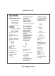
EQUIPMENT LIST LIST OF EQUIPMENT Common Hand Tools Slotted-Head Screwdriver 1/8" tip x 4” blade 3/16" tip x 4” blade 1/4" tip x 6" blade 5/16’ tip x 8” blade Phillips-Head Screwdriver No. 0 tip x 2-1/2 blade No. 1 tip x 3’ blade No. 2 tii x 4” blade Standard Hammer - 16 oz.
INSTALLATION INFORMATION GENERAL INFORMATION Wiring Use #22 AWG minimum for sensor wiring and digital communicator channels. Use #18 AWG minimum for AC power. All wire should be UL-listed Environment The system is designed to work in an indoor heated environment (40 to 120 degrees F.) Battery life may be significantly reduced if components are in direct sunlight or in an unheated location. U.L.
All sensor loops connected to any transmitter should be within the same room. The IEI-510UL glass break detector should be used for the auxiliary output. NOTE: The glass break sensors should be installed with a IEI-515 tester.
INSTALLATION STEPS I STEP 1 Meet the Customer - Confirm Correct Location NOTE: See Customer Relations Section - page 2-l. Make sure that the customer understands what you’re going to do. STEP 2 Do a Walk-Through with the Customer Confirm any questionable placements such as keypad height with the customer. Be sure that the customer is aware of any deviations from what the salesman has told him/her.
STEP 5 Choose Central Controller Location Choosing the appropriate location for the Central Controller is critical to the proper functioning of the system. The Central Controller should be installed in the center of all the transmitters, not necessarily in the middle of the house. It should not be placed near any large metal objects, nor in the range of appliances that generate RF interference. Typical appliances that may be sources of RF interference are: . . . . Personal computers and their modems.
Note: The operation of HAM radio equipment can cause serious interference which can not be avoided by moving the Central Controller. Avoid these Avoid installing the Central Controller near these large metal objects: . MetaI kitchen or bathroom cupboards . Refrigerators . MetaI sinks and tubs . Metal furniture . Foil backed insulation . Foil wallpaper . Large metal ductwork if there are metal doors or other such moveable metal objects, test with the doors both open and closed.
Possible Central Controller and Transmitter Locations Transformer Supervised Smoke PIRT with Curtain Lens I--LIVING ROOM 4 m P @!I Universal Transmitter Ial Wireless Remote Transmitter @!I Keypad Transmitter Central Controller ISI Wireless Siren Controller AT&T Proprietary Information 2-12 GARAGE I
Antenna Placement The antenna for the Central Controller must have a minimum length of 7 feet and should be run in an area central to all the transmitter locations. Increasing the length of the wire does not proportionally increase the effectiveness of the reception. Short increases in length run toward the weakest RF link can increase reception, however, extra long antennas can actually decrease reception. It is best to keep the antenna length less than I5 feet, if possible. Poor reception can.
Possible Antenna Run in a Multi-level Home Central Controller / Antenna Attachment Transformer Antenna Run Down Stackable AT&T Proprietary Information 2-14
Sample Antenna Run in a Single Level Home I u I KITCHEN Transformer Antenna Run DINING LIVING ““” B4r-l GARAGE Central Controller I AT&T Proprietary Information 2-15
BUILDING CONSTRUCTION CONSIDERATIONS Although the 40.68 MHz band is relatively immune to most small metal objects in the home or installation site, some house have building materials that must be taken into consideration. Often, it is a combination of several of these factors that cause problems. Some problems to watch out for. Concrete and brick with metal reinforcement .
STEP 6 Install the Central Controller Before you begin learning about how you will install the Central Controller, take a look at the diagram below. Here we’ve shown you the DIP SWITCHES which will need to be set (or programmed). You can also see by the pointers where there switches are located. Hard wired loop option Hard wired loop optionI Internal sounder setting Interior zone sensors setting I u N House code AT&T Proprietary Information 2-17 I I I 1.
A. Program the Central Controller 1. Set the House Code DIP switches. The HOUSE CODE is used to distinguish components in one system from those in a neighboring system. It must be the same for every component in a given system. Seven DIP switches are used to program the house code. Caution: it would be easy to program the House Code upside down. Be sure the transmitter is correctly oriented before starting.
House Code DIP SWITCH Combinations House Code House Code Dip Switch Settings 1 2 3 4 5 6 7 House House Code Dip Switch Settings 1 Code 2 3 4 5 6 7 000 001 002 003 OFF OFF OFF OFF OFF OFF OFF OFF OFF OFF OFF OFF OFF OFF OFF OFF 032 033 034 035 OFF ON OFF ON OFF ON OFF ON OFF OFF OFF OFF OFF OFF OFF O F F OFF OFF OFF ON OFF OFF ON O F F OFF OFF ON ON 004 OFF OFF OFF OFF OFF OFF OFF OFF OFF ON OFF OFF ON OFF OFF ON ON OFF ON ON 036 007 OFF OFF OFF OFF OFF OFF OFF OFF ON ON ON ON OFF OFF O
House Code DIP SWITCH Combinations House Code House Code Dip Switch Settings 1 2 3 4 5 6 7 House House Code Dip Switch Settings Code 1 2 3 4 5 6 7 064 065 066 067 ON ON ON ON OFF OFF OFF OFF OFF OFF OFF OFF OFF OFF OFF OFF OFF OFF OFF OFF OFF OFF ON ON OFF ON OFF ON 096 097 098 099 ON ON ON ON 068 069 070 071 ON ON ON ON OFF OFF OFF OFF OFF OFF OFF OFF OFF OFF OFF OFF ON ON ON ON OFF OFF ON ON OFF ON OFF ON 100 101 102 103 ON ON OFF ON ON OFF ON ON OFF ON ON OFF 072 073 074 075 ON O
2. Set the Options DIP switches by following these guidelines: Switch 1 sets all system transmitters in the interior zone to either of the following ON = interior delayed OFF = interior instant Switch 2 determines whether the Central Controller’s internal sounder is on or off during an intrusion alarm.
Central Controller Terminal Strip USE UL LISTED COMPONENTS 12.0 to 14.5 VDC MAX I 1 2 3 4 d600 mA TOTAL wired Horns Power Out sensor Sirens (12VDC) (12VDC) loop (+) (-) (+) (-)) (-) (+) 5 6 Digital Communicator Output CHANNELS 1 2 3 4 5 6 7 8 7 10 11 12 13 14 15 16 17 18 19 20 27 22 1 Intrusion Fused 3/4 A IMPORTANT NOTE: There are two versions of the Model 8720 Central Controller.
STEP 7 Install the Digital Communicator NOTE: The 8700 Digital Communicator is probably installed. If it’s not, please follow these steps. Color 1. Plug the 8 wire ZONE INPUT connector into the Digital Communicator. 2. Plug the polarized 2 wire power connector into the Digital Communicator. 3. Peel off the protective backing from the two adhesive strips on the back of the Digital Communicator, Mount the Digital Communicator in the lower right hand side of the AT&T 8720 Central Controller. 4.
CAUTION: If it is necessary to change the time of the first test 6. ) The red LED (DS1) on the Digital communicator should be blinking to show normal operation. The LED will not light if there is no DC power. A steady LED means the Watchdog circuit has detected a processor or memory problem. Reset the watchdog with the AT&T Model 8710 Digital communicator Programmer or AT&T Model 8711 Remote Programming Package. 7. 8. T(red) = i n c o m i n g Tip Connect terminal to earth ground.
STEP 8 Run the Central Controller Antenna Choose the antenna run Apply the information presented in the Installation Information section to the house in which you are installing the system. It is critical that you identify: - Sources of possible RF interference - Potential blocks to RF waves Identify the transfomer location Find a common unstitched household outlet that is close to the antenna run.
STEP 9 Power Up the Central Controller CAUTION: BEFORE YOU POWER UP, PROGRAM AT LEAST ONE WIRELESS REMOTE/TRANSMITTER SO YOU CAN IMMEDIATELY ENTER THE INSTALLER TEST MODE. Attach the Central Controllet antenna to the transfomer Use only a 16 VAC transformer, Comcode number 845402734. Plug in the Transformer Plug the transformer into the 120 VAC, 60 Hz, wall outlet and secure to the waII using the 6-32 screw provided. CAUTION: The transformer is fused, so be careful not to short’ the leads.
STEP 10 Enter the Installer Test Mode a. Enter the transmitter security code and then press the OFF key to put the system in the OFF state. b. Press the Test/Demo key on the Central Controller. The digital display will show an ‘88’. Note: Quickly press the Test/Demo key. If it’s held down for more than 3 seconds, the Demonstration Mode will be entered instead of the installer Test Mode and a “-0.” will appear in the digital display. c.
STEP 11 Choose Transmitter Mounting Locations Wireless Remote/Transmitter and The normal mounting height for the Wireless Remote/Transmitter Keypad Transmitter and the Keypad Transmitter is between 4-l/2 to 5-l/2 feet for convenient access to the keypads. Avoid mounting on metal door or window frames. Universal Transmitterr Universal Transmitters should be mounted at a height of at least four feet. A higher installation produces the best radiation pattern. Avoid mounting on metal door or window frames.
NOTE: Avoid hot and cold air currents. Mount the unit at least three feet from strong forced-air heaters, air conditioners, or sources of drafts such as doors.The hot or cold air currents may cause false alarms, since the detector will sense a rapid change in temperature. . Choose a location at right angles to an intruder’s path. The PIRT has optimal detection when placed so that an intruder’s path would be directly across the detection pattern. . Avoid large objects that may obstruct the lens.
PIRT WIDE-ANGLE LENS COVERAGE ZONE Main Intermediate Lower Lookdown AT&T Proprietary Information 2-30
The curtain lens provides a long and narrow field of coverage for hallways and other such narrow areas.
NFPA Recommendations for Detector InstalIation: Supervised Smoke Detector Transmitter (SSDT) The Nation Fire Protection Association’s Standard 74, Section 2-l, reads as follows: ‘2-1.1.1: Smoke detectors shall be installed outside of each separate sleeping area in the immediate vicinity of the bedrooms and on each additional story of the family living unit, including basements and excluding crawl spaces and unfinished attics. The provisions of 2-1.1.
Other Installation Considerations: To minimize the risk of fire causing injury, loss of life or property, detectors should be located on every level of the home from the basement to the attic, (furnished or unfurnished), and in every sleeping area. More specifically, detectors should be located: . Between sleeping areas and potential sources of fire such as the kitchen, garage, basement or utility room.
TYPICAL SUPERVISED SMOKE DETECTOR PLACEMENT IN A MULTILEVEL HOME Smoke Detectors For Minimum Protection Smoke Detectors For Additional Protection Heat-Activated Detectors 0 0 BED ROOM BEDROOM A A El UVlNG Cl-h.
To avoid false or improper operation, don’t install detectors in the following areas: . Bathrooms. Excessive steam from a shower may cause nuisance alarms. - Directly outside bathrooms. - Too near forced-air ducts used for heating or air conditioning. Air movement may prevent smoke from reaching the detector. . Near furnaces of any type. Air and dust movement and normal combustion products may cause a nuisance alarm. - The peak of an A-frame type of ceiling.
1. STEP 12 Perform RF Link Tests on all locations Use a pencil to press either the Home, Away, or Off key on the Wireless Remote/Transmitter. TransmitterLocations 2. Listen for the proper number of indication beeps from the Central Controller. 3 Beeps 2 Beeps No Beeps - Excellent RF Link. Marginal RF link. The transmitter should be relocated. No RF message was received. A different location must be chosen. 3 Check the Central Controller to verify that the proper transmitter I.D. number appears. 4.
STEP 13 Install Sensors that Utilize the Central Controller hardwired Loop and Auxiliary Power 1. 2. Select sensor location. Remove all power to Central Controller before installing sensor. 3. Connect hardwired loop sensor wire to the Central Controller. . 4. Use screw terminals 5 and 6. Connect auxiliary power wire to the Central Controller. . Use screw terminals 11 (+) and 12 (-). 5. Reconnect power to Central Controller. 6. Test the sensor to see if it causes an alarm.
STEP 14 Run the Phone Line for the Digital 1. Locate the phone line protector block. Communicator 2. Install an RJ3lX block. do not mount the RJ3lX inside of the Central Controller. Follow all manufactured installation procedures. 3. possible, to the phone protector block and attach at both ends. 4. Attach connecting cord from the Digital Communicator to the RJ3lX block.
STEP 15 Install Optional Auxiliary Sounding Devices CAUTION: The Central Controller provides a total of 600 MA to be shared by the digital Communicator, auxiliary sounding devices, and one other sensor that may require auxihy power. Do not exceed this total. Select location for the auxiliary sounding device Follow manufacturer installation procedures Connect the auxiliary sounding device to the Central Controller Use screw terminals 7 (+ ) and 10 (-) for the sounding device.
Using The High Power Siren Relay Module HARD I ;; :A,, j 1 2 3 / S;;;;R W’RED 4 5 6 ~-600 mA T O T A L - : :’‘ IRE, ‘ VDC) j 7 (12VDC) “‘r” 7 10 11 12 (12VDC) “ ,“‘ 13 14 ~ 2 3 15 16 17 C;ANNy 6. + BROWN s‘ \ all I 12 VOLT STANDBY BATTERY 1 ._ 1,l .I SIREN TERMINALS JJ RED 4 BROWN r\ y BLUE NOTE 1 lwREARElviovEmoNsoFl?iEMoDEL87zocENlmL HIGH-POWER SIREN RELAY MODULE HIGH-POWER SIREN NOTE 2 CONFClJ?htlNG TC U.
If the auxiliary sounding device Use the following procedure: requires more powcr than 450 MA, then install the High Power Siren Relay Module 1. Peel off the tape backing. 2. Mount anywhere on the inside of the Central controller plastic housing. Do not mount on a metal surface. 3. Connect the red and black wire leads to a UL-listed external power supply. 4. Connect the blue wire to the Central Controller screw terminal 7( +). 5.
An easy way to program the transmitters is to begin by setting the I.D. code for each one while you have them all together (in the kitchen of wherever you’re working). That way, since you can look at them ail at once, you’ll be sure not to give the same I.D. number to more than one transmitter. STEP 17 Program the Transmitters Let’s look at the I.D. Code for a moment. Identification Codes Each transmitter in the system must have a unique code number.
Use the Zone Locator Card (shown below) to record (IN PENCIL PLEASE - neatly and accurately) the I.D. codes of each transmitter as soon as you set them. This card should be placed in the slot at the back of the Central Controller just as soon as you finish filling it out so it will always be available for the customer's or your company’s use.
Prepare the Wireless 1. Remote/Transmitter for Programming Remove the backplate from the Wireless Remote/Transmitter Press the release tab on the transmitter backpiate. 2. Program the transmitter.
. Set House Code/Option DIP Switches: Switches -17 set the house code. Switch 8 sets the selectable sensor loop zone to either of the following ON = interior OFF = perimeter delayed . Set ID/Options DIP switches: Switches 1 - 5 set the transmitter identification number. Switch 6 sets the selectable sensor loop to either of the following ON OFF = open loop = closed loop Switch 7 sets the battery saver function is used when a sensor is commonly activated many times on a daily basis.
. Set the security code: a. Determine the 3-digit security code. Consult the customer before programming the security code to determine: _ The number of different security codes to be used. For example, the customer may want a different number for each transmitter or one number to be used throughout the system. Any particular numbers that the customer would like to use. A number with personal meaning may be chosen so that it will be easy to remember.
b. Plug each security code post into the slot for the number desired. Blue Wiie = First Number White Wire = Second Number Yellow Wire = Third Number NOTE: The proper wire sequence is easy to remember since the alphabetical order of the colors is the same as the order of the numbers they represent: 1st = B 2nd = W 3rd = Y 3. Check the voltage on the 9 volt battery using your meter. It should register 9 volts. Then connect the 9 volt battery. Check the current draw. 4.
7. b. Press the Test/Demo key on the Central Controller. The digital display will show an "88". C. Within 2 seconds, touch all four keys on the Central Controller at the same time (Messages, Clear Display, Cancel, and Test/Demo). The digital display will show a ‘CC”. d. Listen for the Installer Test Mode indication beeps to start. There will be one beep every forty seconds. Perform the Wireless Remote/Transmitter RF link test. a. Use a pencil to press either the Home, Away, or Off key. b.
Remove the backplate from the Keypad Transmitter. 1. Prepare the Keypad Transmitter Press the release tab on the backplate. Program the Keypad Transmitter. 2. . Set the House Code DIP switches. . Set the ID/Options DIP switches: Switches 1 - 5 set the transmitter identification number.
Switch 7 sets the battery saver function to either of the following: ON OFF = battery saver on = battery saver off Switch 8 should be set ON for high security to allow for the RF link test.
_ Set the security code: a. Determine the 3-digit security code. b. Plug each security code post into the slot for the number desired.
3. Test battery, under load, then connect the 9-volt battery. It should register 9 volts on your meter. Check the current draw. 4. Log the transmitter location on the central controller Zone Locator Card. 5. Temporarily place the transmitter in the area that it will be mounted. Use double-sided tape if necessary. 6. Perform the Keypad Transmitter RF link test. 7. a. Use a pencil to move the slide switch. b. Listen for the proper number of indication beeps from the Central Controller. c.
Prepare the Universal Transmitter 1. Remove the backplate from the Universal Transmitter. Press up on the tab at the bottom of the housing. 2. Program the Universal Transmitter. . Set the House Code DIP switches. . Set the ID/Options DIP switches: Switches 1 - 5 set the transmitter identification number.
Switch 7 sets the battery saver function to either of the following: ON = battery saver on OFF = battery saver off Switch 8 sets the sensor loop zone to either of the following: ON = interior OFF = perimeter instant Switch 9 sets the function of the button on the front of the Universal Transmitter. When set to "panic”, pressing the button will activate an alarm. When set to "test", no alarm is activated. when the button is pressed.
Switches 10 and 11 set the type of alarm that the transmitter will send. Use the chart below to set the transmitter to Intrusion, Fire, Auxiliary, or Environmental. Switch 12 determines whether or not the transmitter is supervised. A supervised transmitter checks in to the central Controller. An unsupervised transmitter doesn’t check in, thus it can be taken off of the premises with out causing a "no check in”.
3. Test the voltage of your 9-volt battery. Connect the battery. Check the current draw. 4. Log the transmitter location on the Central Controller Zone Locator Card. 5. Temporarily place the transmitter in the area that it will be mounted. Use double-sided tape, if necessary. 6. Perform the Universal Transmitter RF link test. a. Use a pencil to press the Alarm/Test button. b. Listen for the proper number of indication beeps from the Central Controller. C.
Prepare the Passive Infrared Transmitter (PIR T) 1. Verify the proper location for the PIRT. Apply the information presented in the Pre-Installation section on PIRT placement considerations. 2. Remove PIRT housing. Press the release tab on the top to the housing. 3. Carefully remove the circuit board from the housing. Press the circuit board release tabs. 4. Choose the proper lens for the PIRT and change the lens if necessary.
5. Program the PIRT. NOTE: The PIRT should be held upside-down for the DIP switches to be oriented properly for programming. . Set House Code DIP switches. . Set ID/Options DIP switches: _ Switches 1 - 5 set the transmitter identification number. Switch 6 should be placed in the OFF position. Switch 7 should be placed OFF in order to set the transmitter for walk-test operation.
Switch 8 sets the transmitter sensor zone to either of the following: ON = interior OFF = perimeter instant Stitches 9 - 12 should be set to the ON position. pscH8$E TRANSMITTER DIP SWITCHES l "Active” Post on PIRT Circuit Board 6. Test the battery voitage. It should be 9 volts. Connect the batteries. Check the current draw. 7. Log the transmitter on the Central Controller Zone Locator Card.
8. Activate the LED by connecting the walk-test LED plug to the ‘Active” post on the PIRT circuit board. 9. Check to see that DIP switch 7 is set in the OFF position. 10. Temporarily mount the PIRT with double-sided tape. Perform the PIRT RF link test. 11. 12. a. Slowly move your hand in front of the PIRT until the walk-test LED comes on. b. Listen for the proper indication beeps from the Central Controller. c.
Prepare the Supervised Smoke Detector Transmitter 1. Verify the proper location for the Supervised Smoke Detector Transmitter. Use the information presented in the Installation Information section to help determine the correct location. 2. Open the detector front housing. Use a screwdriver to bend the release tab that can be accessed through a small hole in the backplate. 3. Program the detector. . Set the House code DIP switches. . Set the I.D. DIP switches.
Use the chart below to set the 3-DIGIT smoke detector identification number. Only I.D. numbers 24 through 31 are available for the Smoke Detectors. ;$t.ns~; 1 24 25 26 27 26 29 30 31 l,D Switch ON OFF ON OFF ON OFF ON OFF ON ON OFF OFF ON ON OFF OFF ring 3 ON ON ON ON OFF OFF OFF OFF 4. Close the detector front housing. 5. Check the voltage on the batteries then connect them. Check the current draw. NOTE: Use only Duracell NM 1604 batteries. 6.
a. Use a pencil to press the Test button on the detector. Hold it down until you hear an alarm tone (approximatety 20 seconds). b. Listen for the proper number of indication beeps from the Central Controller. C. Check the Central Controller to verify that the proper transmitter I.D. number appears. d. Check the status LEDs on the Central Controller for more information..
STEP 18 Mount the Transmitters Mount Wireless Remote/Transmitter 1. Mount the sensor to be used with the transmitter. (Follow the sensor manufacturer’s instructions.) 2. Thread sensor wires through the Wireless Remote/Transmitter backplate. Too much wire can cause the housing to seat improperly and cause false alarms. 3. Mount the backplate. Be careful not to over-tighten the backplate screws. False alarms may result because the housing seats improperly against the tamper switch.
4. Connect sensor wires to the screw terminals on the backplate for the desired type of sensor loop. If wiring the 24-hour sensor loop, the preinstalled jumper must be removed. Otherwise, make sure the 24-hour jumper is firmly installed. 5. Connect the snap caps or spade lug wires to the screw terminals. The snap caps and wires are color coded for each terminal. CAUTION: The wires should not end up on top of (or under) the ] battery or on the tamper switch - could cause false alarms. 1 6.
7. Perform the sensor activation RF test. This test is used to verify the correct functioning of the sensor and the RF link of the mounted transmitter. Mount Keypad Transmitter 1. a. Activate the sensor. b. Listen for the proper number of beeps from the Central Controller. c. Check the Central Controller to verify that the proper transmitter I.D. number appears. d. Check the status LEDs on the Central Controller for more information. Mount the sensor to be used with the transmitter.
7. Mount Universal Transmitter 1. Perform the sensor activation RF test. a. Activate the sensor. b. Listen for the proper number of beeps from the Central ControIIer. C. Check the Central Controller to verify that the proper transmitter I.D. number appears. d. Check the status LEDs on the Central Controller for more information. Mount the sensor to be used with the transmitter. Follow the sensor manufacturer’s instructions. 2.
3. Mount the backplate. Be careful not to over-tighten the backplate screws. 4. Connect sensor wires, if used, to the screw terminals on the backplate. 5. Connect the snap caps or spade lug wires to the screw terminals. 6. Attach the front housing. 7. Perform the sensor activation RF test. a. Activate the sensor. b. Listen for the proper number of beeps from the Central Controller. c Check the Central Controller to verify that the proper transmitter I.D. number appears. d.
Universal Transmitter Applications UNIVERSAL TRANSMITTER SENSOR LOOP: PANIC APPLlCATiONS SEL ECTABLE I OOP PROGRAMMING UNIVERSAL TRANSMITTER SENSOR LOOP: FIRE APPLICATIONS SF’ FCfABl F LOOP PWXXAMVi%JG I WENWCM UNIVERSAL TRANSMITTER SENSOR LOOP: AUXILIARY APPLlCATlONS SELECTABLE LOOP PROGRAMMING PORTABLE BACKPLATE 1. OPEN CIRCUIT . 2. PANIC BUTTON ENABLED 3.
Mount Passive Infrared Transmitter 1. Mount the PIRT backpiate with #6 screws. For a corner mount, use the mounting guides on the angled sides of the backplate. 2. Attach the front housing to the backplate. Allow the unit several minutes to stabilize. 3. Walk test the PIRT to verify its coverage. (PIRT) a. Reduce the sensitivity of the PIRT by using the sensitivity adjustment knob on the circuit board. (8560 only) Turn the knob counterclockwise. (8560 only) 4. 5. b.
Mount Supervised Smoke Detector Transmitter Remove the back bracket from the detector. 1. Use the release tab marked "Press" to remove back for mounting. 2. Mount the detector bracket. 3. Install the detector onto the bracket. 4. Perform second RF link test. a. Use a pencil to press the Test button on the front of the detector. b. Listen for the proper number of beeps from the Central Controller. C. Check the Central ControlIer to verify that the proper transmitter I.D. number appears. d.
STEP 20 Set the House Code/Option DIP SWITCHES: Program the wireless Siren/Controller - Switches 1 - 7 set the House Code. - Switch 8 determines whether the Witless Siren/Controller’s internal sounder is on or off during an intrusion alarm. ON = OFF = Silent Sound - Switch 9 should ALWAYS be ON. Choose the Wireless Siren /Controller Antenna Run Apply the information presented in the Installation Information section to each individual installation.
Run optional auxiliary sounding device wires to the Wireless Siren/Controller CAUTION: The Wireless Siren/Controller provides a total of 450 MA for auxiliary sounding devices. Do NOT exceed this total. If an auxiliary sounding device(s) is being installed, connect the wires to the terminals labeled ‘ONE OR TWO EXTERNAL SIRENS”. Use the strain relief posts.
Use the 9-volt battery that’s included. BE SURE TO TEST IT FIRST! Connect the Battery 1. Press the internal ‘CANCEL’ button. Hold it for 6 SECONDS. The Wireless Siren/Controller will beep once when the button is pressed and again when it goes into the TEST MODE. Enter the Wireless Siren /Controller Test Mode 2. Listen for the Wireless Siren/Controller Test Mode indication beeps to begin. There will be one beep every 40 seconds. 1. Press the Test/Demo key on the Central Controller. Test the RF Link 2.
STEP 21 Perform the System Test System Test Intrusion Transmitters System Test Hardwired 1. Arm the system to the Away ststate using a wireless Remote/Transmitter. 2. Trip each intrusion transmitter. 3. Listen for the appropriate alarm sounding patterns from the the Central Controller. 4. Use the Wireless Remote/Transmitter to disarm the system. 5. Press the Messages key on the Central Controller to verify that the proper signals were received. 6.
System Test 24-Hour Zone Transmitters RF Scanner 1. Trip each 24-Hour zone transmitter (tire, panic, auxiliary, environmental). 2. Listen for the appropriate alarm sounding patterns from the Central Controller. 3. Reset the alarm system (disarm or cancel). 4. Press the Messages key on the Central Controller to verify that the proper signals were received. 5. Call the Central Station to verify that the proper channel and account code were received.