
Installation manual


o
o
Cables
To
The
9370
Processors
The
following
cables
are
ordered
with
"Group
Numbers"
identified
on
the
specification
pages
of
the
System/370
channel-attached
device.
Conn.
Feature
ID
Comments
Notes
6003
2
Channel
0,
Bus
&
Tag
1,2,3,4
6003
4
Channell,
Bus
&
Tag
1,2,3,4,5
6003 6
Channel
2,
Bus
&
Tag
1,2,4,5
6003 8
Channel
3,
Bus
&
Tag
1,2,5
6003
10
Channel
4,
Bus
&'Tag
1,2,5
6003
12
Channel
5,
Bus
&
Tag
1,2,5
6003
14
Channel
6,
Bus
&
Tag
1,2,5
6003 16
Channel
7,
Bus
&
Tag
1,2,5
6003 18
Channel
8,
Bus
&
Tag
1,2,5
6003
20
Channel
9,
Bus
&
Tag
1,2,5
6003
22
Channel
10,
Bus
&
Tag
1,2,5
6003
24
Channel
11,
Bus
&
Tag
1,2,5
6001 26-56
Power
Sequence
and
6,7
Control
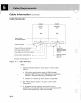
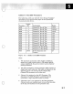
Figure
5-3.
Cables
to
the
9370
Processor
Notes:
1.
The
maximum
cumulative
cable length available to
attach up to eight control
units
is 122 meters (400 ft),
unless modified by the general control unit-to-channel
cabling schematic.
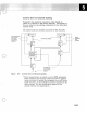
2.
The
block multiplexer
channel
(Feature 6003) contains a
single card
and
a cable set. The cable set connects to the
channel
card on one
end
and
to the
channel
box
(System/370) connector on the other end.
3.
Channel
0 is optional on the 9373 Processor.
The
channel
on the 9373 Processor is restricted to two
controllers: a tape controller
and/or
a printer.
4.
Channels 0
and
1 are optional on the 9375 Processor.
Channel
cards are
installed
only
in
two
of
the five slots
of
the top card enclosure
in
the processor
unit.
5-7