
Installation manual


System
Cabling
5-6
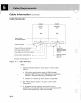
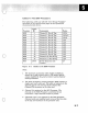
Channel
Cables
Figure
5-2
and
"Cables
To The; 9370
Processors"
on
page
5-7
relate
the
cable
group
numbers
and
feature
code
numbers
to
connector
IDs.
If
you
know
the
features
on
order,
the
cabling
schematic
shows
most
of
the
information
needed
for
ordering
external
cables
from
the
channel
I/O
device.
The
feature
code
(Features
6003
and
6001)
and
connector
IDs
of
the
cables
"To"
the
9370
Processors
are
shown
on
the
right
(connector
ID =
even
number).
For
more
information
on
the
channel
cabling
charts,
see
Chapter
6
of
the
IBM
General Information
Manual,
Installation
Manual-
Physical
Planning,
GC22-7072.
9370
ID
10
FC
2
.....
....
6003 Channel o (Bus and Tag)
4
.....
....
6003 Channel 1 (Bus and Tag)
6
...
....
6003
Channel 2 (Bus and Tag)
8
...
....
6003 Channel 3 (Bus and Tag)
10
.....
....
6003 Channel 4 (Bus and Tag)
12
.....
....
6003
Channel 5 (Bus and Tag)
14
...
....
6003
Channel 6 (Bus and Tag)
16
.....
....
6003
Channel 7 (Bus and Tag)
18
.....
....
6003
Channel 8 (Bus and Tag)
20
""""-
I"'-
6003
Channel
9 (Bus and Tag)
22
.....
....
6003
Channel 10 (Bus and Tag)
24
.....
....
6003
Channel
11
(Bus and Tag)
26-56
.....
....
6001
Power
Sequence and
Control
Figure
5-2.
Channel
Cabling
Chart
0