
Installation manual
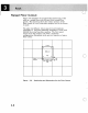
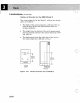

Raised
Floor
Cutout
3-6
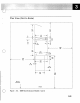
Figure
3-6
identifies
the
recommended
positioning
of
the
rack
on
a
raised
floor
with
6ID-mm (24-in)
raised-floor
panels.
This
drawing
shows
the
relative
position
of
the
floor
cutout;
it
is
not
a
machine
template
and
is
not
drawn
to
scale.
The
plan
view
(Figure
3-2
on
page
3-3)
and
templates
(Appendix
D,
"Physical
Planning
Templates")
of
the
rack
identify
the
actual
machine
opening.
The
floor
panel
cutout
is
for
the
primary
rack
with
a
maximum
configuration.
Secondary
racks
may
not
require
as
large
a
floor
cutout.
Front
+
+
9309-1,2
+
Top
+
~
Floor
------
~.········>\i;i·
.•
·•·•··•··
•.
····.··············l
127
Cutout
I~
45Z
~I
T (5)
(18)
Figure
3-6.
Positioning
and
Dimensions
for
the
Floor
Cutout
o