
Installation manual

r---------------------------------------------------------------------------------------------------------------------------r~;-----------------------------
!
f-
.....
------
..
-----
...
-------------------------
...
------------------
...
------------------------
..
-------------
.....
-----------
...
--------
..
----
...
----
.....
------j
i
Rear
1 c
Left
Side
©
+
Stabilizer
+
@
+
+
+
+
Stabilizer
i
Stabilizer
d
t
______________________
J
Right
Side
b
Front
b'
L
_______________
J
_____________________________________________________________________________________
..
_____
..
_______________________
...
_________________________
1
________________
:
\
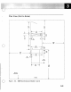
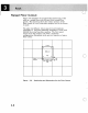
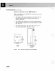
Clearances
for
Service
and Weight Distribution
Figure
3-3.
Plan
View
for
Multiple
Racks
3-4
During
installation
of
a
multiple-rack
system,
when
looking
from
the
front
of
the
racks,
identify
the
racks
in
a
right-to-Ieft
manner
beginning
with
the
letter
A (see
Figure
3-3).
The
rack
letter
has
no
significance
other
than
to
identify
the
racks.
Identifying
the
racks
will
help
you
when
you
run
cables
from
rack
to
rack.
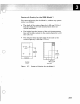
Allow
enough
clearance
to
the
right
of
rack
A
for
another
rack
if
you
have
plans
to
upgrade
your
9375
Processor
to
a 9377
Processor.
The
space
is
also
required
when
upgrading
the
9377
Processor
with
additional
I/O
Bus
Units.
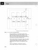
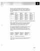
Figure
3-3
and
Figure
3-4
identify
the
required
service/weight
distribution
clearance
required
for
a
o
o