
Installation manual

The
IBM
9309
Rack
holds
standard-sized
electronic
equipment
and
distributes
power
for
this
equipment.
All
models
conform
to
the
EIA
(Electronic
Industries
Association)
RS-310-C
standard
for
racks,
panels,
and
associated
equipment.
Refer
to
the
following
symbols
and
to
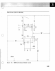
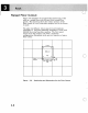
Figure
3-2
on
page
3-3
for
the
plan
view
of
a
one-rack
system.
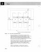
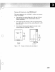
Refer
to
Figure
3-3
on
page
3-4
for
the
plan
view
of
a
multiple-rack
system.
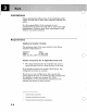
Warning:
.
Be
sure
to
read
"Limitations"
on
page
3-8.
This
contains
important
information
on
the
requirements
for
the
rack.
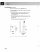
The
symbols
used
in
the
plan
views
are
in
Fig.
3-1.
Cable Entry and Exit
Area
(Base of
Machine)
Power
Cord
Exit
(See Note.)
Standard
Equipment
Outline
(Shows
machine
with
covers
closed.)
+
I~
Service
Area
Boundary
(Service
clearances
are
measured
from
machine
with
covers
closed.)
Casters
Single-Hinged
Door
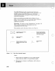
Figure
3-1.
Plan
View
Symbol
Legend
3-2
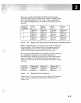
Notes:
1.
Power cords are
supplied
in
4.3 m (14 feet) lengths,
unless otherwise noted
in
the specification pages.
2.
Dimensions are
shown
in
millimeters,
with
inches
in
parentheses.
o