
Installation manual

;,lhf'ritJifdctitin';
~
-:;-.,
,"
".,
:,«,."
-,'(
<>
"'\
"
~.",
h
<'
"~:~~L:;_L:~t~L;:~~2'~~~i::
.:~~~<~~
..
::
~:::;~~:t.,,:':~~.::sv>.:?::_
b.~'A
lMx~<;,":;~~~~ij::~,~,c'::9
"',,,
~
Making
the
Layout
(Continued)
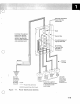
•
Showing
the
height
of
the
raised-floor
above
the
base
floor.
Note: The raised-floor
height
should
be between 155
millimeters
(6
inches)
and
460 millimeters (18
inches).
This
height
should
accommodate
piping
and
power
distribution.
The
minimum
raised-floor
height
for the 9370 system,
with
the System/370
channel
feature,
is
155 millimeters
(6
inches).
However, the
height
should
also have a
minimum
of
an
additional
115 millimeters (4.5 inches) to ensure
you
can
run
cables
and
connectors over
and
under
obstacles.
When a raised-floor
panel
is cut for cable
entry
or
air
register,
additional
panel
support
may
be
required to restore
structural
integrity. See
Figure
3-6 on
page
3-6 for the recommended floor
cutout
dimensions
and
placement.
Tasks
that
you
must
do
for
a
non-raised-floor
environment
include:
•
Showing
the
planned
placement
of
cables
for
minimum
obstruction.
•
Showing
the
amount
of
additional
cable
required,
if
the
cable
route
is
indirectly
between
units
(such
as
along
walls
or
suspended).
•
Deciding
if
you
need
cable
guards
or
ramps
to
ensure
personnel
and
equipment
safety.
Always
review
the
final
layout
to
ensure
that
cable
lengths
do
not
exceed
limitations
and
that
all
devices
have
proper
clearances.
Notify
IBM
immediately
of
any
layout
changes
that·affect
cable
lengths.
Storage
and
Shipping
Environment
1-6
IBM
designs
its
units
to
operate
in
a
controlled
temperature
and
relative
humidity
range,
and
(even
when
stored
or
in
shipment)
they
require
some
environmental
control.
If
you
store
the
unit
outside
the
specified
limits,
permanent
damage
can
result.
c
o