-- --------------_ .- 9370 Information System Installation Manual Physical Planning , r ..
GA24-4031-0 File No. 9370-15 o IBM 9370 I nformation System Installation Manual Physical Planning o o ---.- ---------------,-- ----~-- -.
Federal Communications Commission (FCC) Statement Warning: This equipment generates, uses, and can radiate radio frequency energy and if not installed and used in accordance with the instruction manual, may cause interference to radio communications. It has been tested and found to comply with the limits for a Class A computing device pursuant to Subpart J of Part 15 of FCC Rules, which are designed to provide reasonable protection against such interference when operated in a commercial environment.
Who Should Read This Book This book contains information necessary for you to prepare the physical site and plan for installing the 9370 system. Become familiar with the contents of this manual before beginning any installation planning. «'tAW How to Use This ,Book This book has six chapters and four appendixes: Chapter 1, "Introduction," provides general information on site preparation and customer responsibility.
What You Should Know The system hardware consists of: • • • • • • The 9309 Rack Enclosure. The following IBM 9370 rack-mounted System/370 processors: 9373 Model 20 9375 Models 40 and 60 9377 Model 90. Integrated input/output (I/O) controllers for: Disk/Tape Work stations Telecommunications Local area network. Direct access storage devices (DASD). Magnetic tape drive units. System/370 block multiplexer channels.
1. Introduction . . . . . . . . . . . . . . . . . . . . . . . . . . . . . 1-1 Your Responsibilities ................................ 1-3 Planning the Layout ................................ 1-3 Planning Checklist ................................. 1-5 Making the Layout ................................. 1-5 Storage and Shipping Environment ..................... 1-6 Electrical Power ................................... 1-7 Primary Computer Power Service .................... 1-7 8ranch Circuits .................
5. Cable Requirements . . . . . . . . . . . . . . . . . . . . . . . Cable Information ................................. . Channel Cable Length ............................ . Coaxial Cable Length ............................ . Communication Cable Length ...................... . Cable Schematic ................................ . System Cabling ................................... . 5-2 5-2 5-2 5-3 5-4 5-6 5-1 6. Remote Facility . . . . . . . . . . . . . . . . . . . . . . . . . . . General Information ......
r?q'rY'Tf;:'t:'t'~'T;,~'~~~<";0'''~:,",,'';'' ~..,,,.'?>,.,_,,,~=_~~_~v_ ~~7·'":':<-~~~~·''''' .«"~o<~" ~~'''::~wl ~".v'.. ~"'»>':~~w":"»:»,~,v,,,,~.:_.,,,~,«,= '«F" N~Y«'~=< "'''>'''' <' ,;;~~~ :. .'" '-:'-~'~":C= 'U.* '--: 77;,~::;·~t:· ':···v<,:,:·~ ~ ':;;::' "':~':>':: >.;,,, :;:1";:: :'~: r;:~ Fig No. 1-1. 2-l. 2-2. 2-3. 3-1. 3-2. 3-3. 3-4. o 3-5. 3-6. 3-7. 3-8. 4-1. 4-2. 4-3. 4-4. 4-5. 4-6. 4-7. 4-8. 4-9. 5-1. 5-2. 5-3. 5-4. 5-5. 5-6. 6-1.
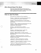
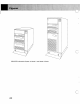
B b 0 CD c: CJ ~ 0 §= ==: t:J ~ ~ ac=:ss - ::::: -==: en :::= [J IJ ~ ~ ~ Q ----------- --~ C IBM 9370 Information System in Model 1 and Model 2 Racks c" viii
Your Responsibilities ................................ 1-3 Planning the Layout ................................ 1-3 Planning Checklist ................................. 1-5 Making the Layout ................................. 1-5 Storage and Shipping Environment ..................... 1-6 Electrical Power ................................... 1-7 Primary Computer Power Service .................... 1-7 Branch Circuits .................................. 1-8 Grounding .....................................
' ':- >, ,,"- -< ,.~ " ; .. <:..,,,,, ,> ';' , i.~. " , ;-~,;"" ~" ~,:.: <'.).'".':;:.- ~.':< '::~:<>.,.-. ,.,; The 9370 system includes the 9370 Processors, which are air-cooled, compatible with System/370, and reside in the IBM 9309 Rack Enclosure (for clarity, rack will be used in the rest of this book). There are four versions of the 9370 Processor. • • • 9373 Model 20 9375 Models 40 and 60 9377 Model 90.
Your Responsibilities Site preparation for the system is your responsibility. This book can help you prepare for installing and expanding your system. Although you are responsible for this activity, you may need help from IBM, consultants, contractors, or vendors to complete the tasks. The primary task of the site planner is to identify the physical space and system layout requirements for the equipment. Appendix D, "Physical Planning Templates," supplies paper cutouts of the rack to help plan the layout.
Planning the Layout (Continued) • Priority of channel-attached devices • Space limitations, such as floor-loading capacity, location of columns, and provisions for growth • The length of the cables connecting the units in the system • Visual access required between a control unit and at least one of its associated I/O devices • Work space and aisles. You may need to prepare and analyze several layouts before choosing the final layout.
Planning Checklist The planning checklist (Appendix C, "Planning Checklist") provides a suggested schedule. Your site preparation may not require all of the suggested steps, or you may require some additional steps. Be sure you allow enough time to complete the necessary steps before your system arrives. Making the Layout o The prepared layout must be accurate and drawn to scale.
;,lhf'ritJifdctitin'; ~ -:;-., ," "., :,«,." -,'( <> "'\ " ~.", h<' "~:~~L:;_L:~t~L;:~~2'~~~i:: .:~~~<~~ ~:::;~~:t.,,:':~~.::sv>.:?::_ b.~'A lMx~<;,":;~~~~ij::~,~,c'::9 "', , ~ .. :: Making the Layout • (Continued) Showing the height of the raised-floor above the base floor. Note: The raised-floor height should be between 155 millimeters (6 inches) and 460 millimeters (18 inches). This height should accommodate piping and power distribution.
Warning: Do not store a unit in a room that has chemicals that can cause corrosion damage. See "System Environmental Specifications" on page 2-7, and individual specifications in Chapter 4. When removing a unit for shipment or storage, use the blocks, braces, and preparation procedures found in the Packaging Bill of Material. This is a protective package designed uniquely for each unit, and is available from any IBM Branch Office.
Electrical Power (Continued) o Branch Circuits The branch circuit panel for the computer should be in a convenient, well-lighted area of the computer room. Protect the individual branch circuits on the panel with circuit breakers properly rated according to the manufacturer's specifications and applicable codes. Label each circuit breaker to identify the branch circuit it controls.
Remotely Operated Power Service .4""'=c-.t--+--+- M a in Incoming three-phase power from service entrance or derived system, appropriate over-current protection and suitable ground. Ci rcuit Breakers of Appropriate Size Grounding Terminal Bar (Bonded to Enclosure) o Neutral Ground Service Entrance Ground or Suitable Building Ground ~Branch Circuits 0-0---0--- * For loads 208/240V Legend: - - - Phase Wires and Neutral ---Insulated Green Wire Ground o Figure 1-1.
Electrical Power (Continued) Grounding A machine must be properly grounded. It is recommended that an insulated green wire ground, the same size as the phase wire, be installed between the branch circuit panel and the receptacle. For some small machines such as terminals, a continuous metallic conduit is adequate for grounding. To ensure proper grounding, a licensed electrician should check the grounding and receptacles for conformance with the country electrical codes.
Convenience Outlets You are responsible for selecting and installing lightning protection devices. Install a suitable number of convenience outlets in the computer room and the service representative area for use by building maintenance personnel and service representatives. Convenience outlets should be on the lighting or other building circuits, not on the computer power panel or feeder. Do not use the service convenience outlets on IBM units for any purpose Qther than normal servicing.
Additional Reference Material • • • (Continued) Air Conditioning Temperature and Humidity Design Criteria Safety and Fire Precautions.
'F.~j.MB·;ilI:~~-~~~--~·~-~~~~-------~~=~SP~:~~;xr.;;;:!,~ :;4{; .. ' ~'O~- Syst&:m;Spec'~:fib~tibns . Primary Rack Power ................................ Power Control Compartment (PCC) .................. Power Phase Imbalance ........................... Plugs and Receptacles: ............. . . . . . . . . . . . . .. USA, Americas Group (AG), and Asian/Pacific Group (A/PG) ..................................... Europe/Middle East/Africa (EMEA) ................ Cooling ...................................
Xi i. .:: . . . »<'<.; ~., ,_ The system includes rack-mounted units and peripheral devices. Refer to the rack and unit specification pages for power and environmental information. The system can operate as a stand-alone computer system or as an information network, connecting to similar systems and/or host computer complexes. The system can support many display terminals and printers, including personal computers. Primary Rack Power You must provide primary AC power for the 9309 Rack.
Power Control Compartment (PCC) The rack has a power control compartment, which serves as a power source for the system units. This unit distributes 120-volt (Modell) and 220-volt (both models) single-phase power to the AC power outlets. There are five versions of the power control compartments. Each version is designed for a specific input power. The requirements for power and control define the various versions of the rack.
Primary Rack Power Max. PCC Rack EIA Model Units kVA Phase 4.4 2* 1 3 1 19 5 2* 5 1 2 Figure 32 2-1. 2.4 4.4 5 5 1 2 2 1 * * (Continued) Main Line CB 10 Amps 15 Amps 15 Amps 25 Amps 20 10 15 25 Amps Amps Amps Amps Country Switzerland EMEA (See Note 2) EMEA (See Note 2) USA, AG, A/PG, EMEA (See Notes.) USA only Swi tzer land EMEA (See Note 2) USA, AG, A/PG, EMEA (See Notes) Specify Code 9114 9112 9113 9111 9115 9114 9113 9111 Power Control Compartment Versions Notes: 1.
'.'/ '"'; ~ ~ * "~""'"'"fJ ..,,, "~, ' ",',~""""".~ "',- o Country Austria Belgium Denmark Finland France Germany Ireland Israel Italy Kuwait and Gulf States N etherlands Norway Pakistan Portugal Saudia Arabia South Africa Spain Sweden Switzerland Turkey UK AREAS/South (AFRICA) ROECE (IBM Regional Office for Europe, Central and East) Figure 2-2.
Primary Rack Power (Continued) Power Phase Imbalance If you have a single-phase power control compartment, you will supply single-phase AC power. However, if you have a two-phase power control compartment, you will have to supply three-phase power. The two-phase power control compartment only uses phases 1 and 2 and the neutral of incoming three-phase power. This may result in a power imbalance for the three-phase power system.
Cooling Directly forced-air cools the unit. The air intake is through the front panel and air exhaust is out the bottom and top of the rack rear door. For maximum system heat output for the rack and each unit, see Figure A-Ion page A-2. To determine the total heat output of your system, identify the units you are ordering and add the heat outputs specified for those units.
o 2-8
Plan View (Not to Scale) .......................... 3-3 Raised Floor Cutout ................................ 3-6 Rack Specifications ................................. 3-7 Limitations ....................................... 3-8 Requirements ................................... 3-8 Appliance Coupler Outlets ....................... 3-8 Center-of-Gravity for A Slide-Mounted Unit .......... 3-8 Center-of-Gravity for the 9309 Model 1 ............. 3-9 Center-of-Gravity for the 9309 Model 2 ............
The IBM 9309 Rack holds standard-sized electronic equipment and distributes power for this equipment. All models conform to the EIA (Electronic Industries Association) RS-310-C standard for racks, panels, and associated equipment. Refer to the following symbols and to Figure 3-2 on page 3-3 for the plan view of a one-rack system. Refer to Figure 3-3 on page 3-4 for the plan view of a multiple-rack system. Warning: . Be sure to read "Limitations" on page 3-8.
Plan View (Not to Scale) ---------------------------------------------------------------------1--------------------------------------~ T 760 (30) 635 (25) L- I ~ I~ 610 (24) T 127 76 (5) (3) 1220 (48) c o 921 (36) ~ + 650 (25 1/2) I I~ I I 26 (1 1/8) -I 635 (25) ~ I I I I I I I I I I 750 (29 1/2) ~----------------, rI I (3) ...
r---------------------------------------------------------------------------------------------------------------------------r~;----------------------------- ! f-.. . ------.. -----.. -------------------------.. ------------------.. ------------------------.. -------------.. . -----------.. -------- . ----.. ----.. .
~/'., ,, ,;' ~ " " '''~" < '"-U-~-""-"-'--'~-"~-'.~~'];-"'-""~:-""'~--"'--'.---'''.'---~i.:"::.;s:;::L:J:..!.l.:-kLii..:i..~~~ floor-load rating of 345 kg/m2 (70 lb/ft2). The clearance assumes each rack has a maximum weight of 478 kg (1,055 lbs). The dimensions for a', b', and c' vary according to the weight configuration and the floor-load rating of your facility. Number of Racks 1-4 5 6 Figure o 3-4. Left a + a' 1220 mm (48 in.) 1525 mm (60 in.) 1525 mm (60 in.) Right b + b' 1220 mm (48 in.
Raised Floor Cutout Figure 3-6 identifies the recommended positioning of the rack on a raised floor with 6ID-mm (24-in) raised-floor panels. This drawing shows the relative position of the floor cutout; it is not a machine template and is not drawn to scale. The plan view (Figure 3-2 on page 3-3) and templates (Appendix D, "Physical Planning Templates") of the rack identify the actual machine opening. The floor panel cutout is for the primary rack with a maximum configuration.
Rack Specifications Dimensions (Model 1) Power Front 650 (25 1/2) Model 1 2 phase mm inches Note: Side 921 (36) Height 1 000 (40) Height is measured from the floor. Floor clearance is 75 mm (2.95 in). 50Hz .093kVA .093kVA 1,3 60Hz .093kVA .093kVA 1 Note: A 3-phase input power control compartment is available for EMEA.
Limitations These requirements reflect some of the conditions under which the rack and its units were tested for stability and safety. It is the responsibility of the customer or unit manufacturer to assure the rack and its units meet these requirements. Failure to meet these requirements could result in an unsafe condition.
Center-of-Gravity for the 9309 Model 1 The center-of-gravity for the Modell, without any system units, is as follows. • The depth of the center-of-gravity is 495 mm (19.5 in.) from the front of the rack (measurement does not include stabilizer). • The height from the bottom of the rack (measurement does not include casters) to. the center-of-gravity is 410 mm. (16.1 in.) • The distance from the right edge of the rack to the center-of-gravity is 292 mm (11.5 in.).
Limitations (Continued) Center-of-Gravity for the 9309 Model 2 The center-of-gravity for the Model 2, without any system units, is as follows. • The depth of the center-of-gravity is 495 mm (19.5 in.) from the front of the rack (measurement does not include stabilizer). • The height from the bottom of the rack (measurement does not include casters) to the center-of-gravity is 657 mm. (25.8 in.) • The displacement from the right edge of the rack to the center-of-g:avity is 292 mm (11.5 in.).
loading the Rack Warning: Always install the system units in a bottom-to-top sequence. If you do not install the system units in this sequence, the rack may become top heavy - depending on the types and location of the installed system units. Power Besides the single-phase power control compartment, a three-phase power control compartment is available for EMEA (Europe/Middle East/Africa) countries.
Limitations • (Continued) Support Slides Some system units mount in the rack by residing on slides. You can extend slide-mounted units. Warning: System units mounted on slides must: Be UL listed/recognized or certified by the eSA Include an attached label that warns the user that the rack may tip if more than one slide-mounted unit is extended in the service position at the same time. This label must be visible to the user when the unit is pulled forward.
IBM 9373,9375, and 9377 Processors .................. 4-2 9373 Processor .................................. 4-2 9373 Processor Specifications ...................... 4-3 9375 Processor .................................. 4-4 9375 Processor Specifications ...................... 4-5 9377 Processor .................................. 4-6 9377 Processor Specifications ...................... 4-7 I/O Card Unit .............. . . . . . . . . . . . . . . . . . . . . . .. 4-8 I/O Card Unit Specifications ..............
IBM 9373, 9375, and 9377 Processors 9373 Processor 356 (14) Figure 4-2 4-1.
9373 Processor Specifications Dimensions: Height: 356 mm (14 in.) Width: 483 mm (19 in.) Depth: 660 mm (26 in.) Weight: 60 kg (132 lb) Heat Output: 588 W (2,000 BTU/HR) Airflow: o 7.9 m 3 /min [280 cubic foot meters (cfm)] Power: 0.70 kVA AC Voltage: 120 and 220 volts Noise-Emission Levels Refer to "Acoustics (Noise-Emission Levels)" on page A-3.
IBM 9373, 9375, and 9377 Processors (Continued) 9375 Processor 711 (28) o Figure 4-2.
9375 Processor Specifications Dimensions: Height: 711 mm (28 in.) Width: 483 mm (19 in.) Depth: 828 mm (33 in.) Weight: 132 kg (290 lb) Heat Output: 1 800 W (6,145 BTU/HR) Airflow: o 17 m3/min (600 cfm) Power: 2.00 kVA Noise-Emission Levels Refer to "Acoustics (Noise-Emission Levels)" on page A-3.
IBM 9373, 9375, and 9377 Processors (Continued) 9377 Processor 711 (28) o Figure 4-6 4-3.
9377 Processor Specifications Dimensions: Height: 711 mm (28 in.) Width: 483 mm (19 in.) Depth: 828 mm (33 in.) Weight: 122 kg (268 lb) Heat Output: 1 200 W (4,100 BTU/HR) Airflow: o 11 m 3/min (380 cfm) Power: 1.70 kVA Noise-Emission Levels Refer to "Acoustics (Noise-Emission Levels)" on page A-3. Operating Environment: Temperature ReI Humidity Max Wet Bulb 15.6 to 32.2°C 20 to 80% 22.8°C (60 to 90°F) (73°F) Nonoperating Environment: Temperature ReI Humidity Max Wet Bulb 10 to 43.
I/O Card Unit 356 (14) o Figure 4-4.
I/O Card Unit Specifications Dimensions: Height: 356 mm (14 in.) Width: 483 mm (19 in.) Depth: 654 mm (26 in.) Weight: 55 kg (120 lb) Heat Output: 211 W (720 BTU /HR) Airflow: o 0.43 m 3/min (15.0 cfm) Power: 0.90 kVA Noise-Emission Levels Refer to "Acoustics (Noise-Emission Levels)" on page A-3. Operating Environment: Same as the 9377 processor. Nonoperating Environment: Same as the 9377 processor. Note: Feature 5010 is a one-bus I/O Card Unit and Feature 5020 is a two-bus I/O Card Unit.
9332-400 DASD Figure 4-5.
9332-400 DASD Specifications Dimensions: Height: 133 mm ( 5 1/4 in.) Width: 483 mm (19 in.) Depth: 592 mm (23 1/3 in.) Weight: 30 kg (65 Ib) Heat Output: 262 W (895 BTU/HR) Airflow: o 1.4 m 3/min (50 cfm) Power: 0.50 to 0.70 kVA AC Voltage: 115 or 230 volts Noise-Emission Levels Refer to "Acoustics (Noise-Emission Levels)" on page A-3.
9335-A01 DASD Controller o Figure 4-6.
« O~~~"'W'«' ~ OW '~'~ mp'ww >'0~~~.~:~: :'f~·!:;;1'~~'?:~·~''''~~~:'7 7> /'.::"~ T~>TTT~:'~~~<~:~~':~:~~;;C:~~~' ~~77::::~~: ;~ " .'c : "," , . ' ~ :~ :::: :" <'<~: ~ ,~ "~ .,." ": <" ',~ ::: \', .'= ;'~,~?~, ,: ',.,. ;.;, :, ,.~;, 9335-A01 DASD Controller Specifications Dimensions: Height: 135 mm (5 1/4 in.) Width: 445 mm (17 1/2 in.) Depth: 560 mm (22 in.
9335-801 DASD 9335-801 DASD 267 (101/2) Figure 4-7.
V«'~"""''W'''':<'«_«=»>'':~l:l*''«o/w<:"<:""«:»>,:".."..,...."".,=,w~,:,';'':,,,,:,,w'''''''''''_'?'~~, ," 7~~~~-, <' ~'~,~<~< <'~~~'--~. ".:: . ,::. ~. ~ ":::'~;-::::-:::·-::::TEE~Em:;~~\ < ;:i 'f, "'" +::f' < ,\ :i,' :~:\, .;;. :":, .~ '".,'; ~ 9335-801 DASD Specifications Dimensions: Height: 267 mm (10 1/2 in.) Width: 445 mm (17 1/2 in.) Depth: 685 mm (27 in.) Weight: . 60 kg (132 lb) Heat Output: 430 W (1,467 BTU /HR) Airflow: o 2.4 m 3/min (85 cfm) Power: 0.
9347 Tape Unit Figure 4-8.
~:~';~;.;;7:~~;-",·"'·~";~~~r-w"'~: ') '/ < , ... " ~ 0 ",.' '-,.y .', ;.)~:":1~~;~ 'v ,:·::~;>::~.r:;~ ";'>< F'.~.~<~ ;'.~ ~ ~ .'".,., " ,;,"'. , . :";' , > ".~, 9347 Tape Unit Specifications Dimensions: Height: 222 mm (8 3/4 in.) Width: 483 mm (19 in.) Depth: 559 mm (22 in.) Weight: 37 kg (82 Ib) Heat Output: 270 W (925 BTU/HR) Airflow: 1.4 m 3/min (50 cfm) o Power: 0.
Power Sequence and Control rj!!,I 80 (3) c Figure 4-9.
Unit Specifications Dimensions: Height: 80 mm ( 3 in.) Width: 434 mm (17 in.) Depth: 217 mm (8 1/2 in.) Weight: 7 kg (15 lb) Note: The power sequence and control unit (Feature 6001) is only available on the 9375 and 9377 Processors. For more information see Chapter 5, "Cable Requirements," and Planning For Your System, GA24-4030.
o o 4-20
Cable Information .................................. 5-2 Channel Cable Length ............................. 5-2 Coaxial Cable Length ............................. 5-2 Communication Cable Length ....................... 5-3 Cable Schematic ................................. 5-4 System Cabling .................................... 5-6 Channel Cables ................................ 5-6 Cables To The 9370 Processors ................... 5-7 Control Unit-to-Channel Cabling ..................
Cable Information When you draw the floor plan of the data processing area, know the location of the external devices so that you can determine the maximum cable lengths. For World Trade, the devices have to be placed according to the standard cable length available. Channel Cable Length Determine the cable length by measuring the cable path from the cable entry/exit cutout of the device/control unit to the entry/exit of the rack.
Communication Cable Length To find the length of the communication attachment, measure from the cable entry/exit hole of the system to one of the following: • The external modem or auto-call unit • The digital-network channel service unit • The teleprocessing line connector • The protective device, where such a device communicates with a switched teleprocessing line.
Cable Information (Continued) Cable Schematic FRONT FRONT Primary Rack Secondary Rack TOP TOP Frame Cutout for Cable Entry/Exit Channel Tailgate Channel I/O Bus and Tag (Note 1) Work Station Cables (Note 2) Power Sequence and Control (Note 3) Communication Cables (Note 4) Multi-Rack Signal and Power Sequence Cables (Note 6) c Channel Tailgate 9377 Only (Note 7) Processor Console (Note 5) Figure 5-1. Cable Schematic Notes: 1. Channel-attached devices.
4. See "Communication Cables" on page 5-10 for required cables. 5. A signal cable for the processor console is shipped with the processor [fixed length: 7.6 meter (25 ft)]. Two additional signal cables for the processor console (and the RSF modem) are shipped with the processor [fixed length: 7.6 meter (25 ft)]. These cables are for the remote support and auto start operations. Auto start operations only become active when the rack has the security key lock installed. 6.
System Cabling Channel Cables Figure 5-2 and "Cables To The; 9370 Processors" on page 5-7 relate the cable group numbers and feature code numbers to connector IDs. If you know the features on order, the cabling schematic shows most of the information needed for ordering external cables from the channel I/O device. The feature code (Features 6003 and 6001) and connector IDs of the cables "To" the 9370 Processors are shown on the right (connector ID = even number).
Cables To The 9370 Processors The following cables are ordered with "Group Numbers" identified on the specification pages of the System/370 channel-attached device. Conn. o Feature 6003 6003 6003 6003 6003 6003 6003 6003 6003 6003 6003 6003 6001 Figure 5-3.
System Cabling (Continued) 5. Channels 0 through 11 are optional on the 9377 Processor. Channel cards can be installed only in the two-bus 110 Card Unit (Feature 5020). The 110 Card Unit can be installed in a secondary rack. Your physical layout will depend on the number of system racks you have. 6. Power sequence and control is an optional feature with the Systeml370 channel feature. It enables 110 control units to power onloff sequentially when the system powers onloff.
Control Unit-to-Channel Cabling Generally, the maximum cumulative cable length to attach to a channel is 122 meters (400 feet). Exceptions to this are noted on the cabling schematics for the individual control units. All control units are serially connected to the channels. Power Sequence and Control" gof~rr;la~~it ............... .. _- ....... .' ------(,' Position) J I Channel 2 F- -?l Channel 1 J I ~ - ~ " ~ I/O Interface Cables ~~ ~ Control Unit No.1 .' - 1 ~, 5-4.
System Cabling (Continued) Communication Cables Figure 5-5 and Figure 5-6 identify the interface and cable length of the Communications Processor (Feature 6030) for the Asynchronous Adapter (Feature 6032) and Multi-Protocol Adapter (Feature 6031). Two other adapters supported by the Communications Processor are the IBM Token-Ring Adapter (Feature 6034) and the IEEE 802.3 Local Area Network (LAN) Adapter (Feature 6035).
Feature 6031 o Qty. 1 6031 1 6031 1 6031 1 6031 1 6031 1 6031 1 6031 1 6031 1 6031 1 6031 1 6031 1 Figure 5-6. Maximum Length 6.0 meters (20 feet) 15.2 meters (50 feet) 6.0 meters (20 feet) 6.0 meters (20 feet) 6.0 meters (20 feet) 6.0 meters (20 feet) 6.0 meters (20 feet) 6.0 meters (20 feet) 6.0 meters (20 feet) 6.0 meters (20 feet) 6.0 meters (20 feet) 6.0 meters (20 feet) Type RS-232 Notes 1,3,4 RS-422 1,3,4 Network X.21 1,3,4 X.21 BIS 1,3,4 DDS V.
System Cabling (Continued) 4. Each Multi-Protocol Adapter supports two lines and each Asynchronous Adapter supports four lines. 5. The maximum configuration for the Communications Processor is: • Any combination, maximum of three, of the Multi-Protocol Adapter and Asynchronous Adapter, or • Four Asynchronous Adapters using the ASCII Subsystem (16 lines), or • One IEEE 802.3 Local Area Network (LAN), or • One IBM Token-Ring Adapter.
.~. x ~ . :/~-....f~~Ii:t~~c:J:rF~§bH:Y>· General Information ................................. Communication Facilities ............................ Requiremerits ................................... Remote Facility .................................... External Interface Adapter (USA only) ................ Customer-Ordering Information For Remote Facility ......
The Remote Facility is a standard feature on all 9370 Processors. In the event the system malfunctions, the Remote Facility allows fast maintenance response. It also allows you to control the processor at a remote location. The Remote Facility provides the following functions: " • Remote Service transfers system error data to the IBM support system. This also allows service representatives to control and analyze the system from a remote location.
General Information To establish a switched network data connection in manual operation, you need a telephone: • To call or answer a call and o To switch the circuit to the modem to transfer the data. The following applies for the USA and Canada: o • You must provide a telephone that uses a modular jack. You should also have the switched network line terminated at your site.
Communication Facilities In the USA and Canada, IBM will provide a 2400 bps, manual dial, auto-answer modem that includes protective coupler circuits as part of the 9370 processor console. You will need to: • Obtain a dedicated switched network line that terminates at an RJll data jack (four-position modular jack). This should terminate within 4.5-meters (15-feet) of the processor console and modem. Note: IBM provides a 4.
< '",'.' ,'."" ";'.' " ",."".,wn
Remote Facility (R.F) External Interface Adapter (USA only) 7.6 Meters (25 Ft) Figure 6-1. PIN 62X3422 1.8 Meters (6 Ft) Power Cord o Remote Facility Configuration Notes: 1. A RS232C/CCITT V.24, Y-shaped cable (PN 62x3422) is shipped with the processor to all countries. 2. All customers must provide a switched network communication line with a compatible telephone. 3. For convenience, install the customer-provided telephone handset next to the display console. 4.
CDT-Type Protective Coupler Modem dependent External Modem Line Connection Line Type IBM 5842 Modem or equivalent (see Note 2) Switched Network Line for data up to 2400 BPS OEM equivalent to V.22 or V.22 bis interface and operation (see Note 1) o Common-Carrier provided before Jan. 1, 1983 Common-Carrier provided USOC as specified by OEM instructions Notes: 1. Additional site planning and preparation may be required before installing the modem or coupler units.
Remote Facility (Continued) Customer-Ordering Informatio,n For Remote Facility 1. Communication Facility Requirements • Line Type - Dial-Up Business Line May be Touch-Tone! or rotary dial • Line Speed - 2400 bps • Line Termination - IBM 5842 Modem (or equivalent) • FCC Registration information - determined by customer-supplied modem 2. Modem Requirements • IBM 5842 or equivalent V.22 bis for the USA and Canada. • CCITT V.22, CCITT V.22bis, or CCITT V.23 modem for World Trade countries. o 3.
o Specification Summary Chart ........................ Acoustics (Noise- Emission Levels) .................... Unit Noise- Emission Levels ..........................
Specification Summary Chart Type 9309 9373 9375 9377 9332 9335 Model 1 2 20 40, 60 90 400 A01 B01 9347 Figure A-1. Unit Description 1.0 Meter Rack 1.6 Meter Rack Processor Processor Processor DASD DASD Controller DASD Magnetic Tape Drive I/O Card Unit Max. kVA 0.093 0.093 0.70 2.00 1.70 0.50 0.24 0.72 0.30 Heat Output W BTU/hr 194 57 194 57 588 2,000 1800 6,145 1 200 4,100 262 895 175 597 430 1,467 925 270 0.
o Acoustics (Noise-Emission Levels) Acoustical data is intended to answer requests for information and is for consultants and planners requiring the data to help predict the levels of acoustical noise. The format in which the data are provided conforms to the standard used by the computer industry. The measurement procedures used to acquire the data conform to American National Standard S12.10-1985 and International Standard 7779. The following terms are used to present acoustical data in this manual.
~\i:IJ.'~(;':::Sp;~Cificati9n •. Sl.lmmary' '''&'4,;;C,~m",,,~,,,,,~LLL:;::*:,~,",_,,'',,~, ~",";'"i,,';,,:,,;, " ,:,; ".M;," ,,';; ,,': >,,~ *"~'" Unit Noise-Emission Levels The following table shows the noise-emission levels for units of the system. The levels for these units were measured in the 9309 Rack Enclosure, Model 2. The information is preliminary and subject to change. Model Hz Type 9309 1,2 9373 20 9375 9377 40 60 90 9332 400 9335 A01 9335 B01 9347 I/O Card Unit Figure A-2.
Noise levels are not additive. Use the following logarithmic formula for the emission level of your system configuration. The formula for the sound power-emission level of a sample configuration consisting of a 9375, 9335-A01, and two 9335-B01s is as follows: Lsum = log [ sum lOLwAd ] log [ 1(J3.6 + 1(J5.8 + 107 . 1 + 107. 1 ) log [ 3981071.7 + 630957.3 + 12589254 + 12589254 } log [ 29790537 } 7.
c o A-6
Appendix B. PlUgs and cReceptac,es:1I Plugs/Receptacles for USA, AG, APG .................. Plugs and Receptacles for EM EA ..................... Three- Phase Power Plug .......................... 50- Hz Power Cord Style ..........................
IBM supplies power cords with attached plugs. You, the customer, must supply the corresponding power outlet receptacles. The reference (Ref) letter in Figure B-1 corresponds to the letter in Figure B-2 on page B-3. Plug Ref Type B 3750 IE] L6-30P II WIP130 iii 56PA330 0 3720U-l iii 5-20P Figure 8-1.
. Plug Receptacle/ Connector 0 (J CD 0 0 0 Q 0 Q ®6® o ee @e Figure 8-2.
Plugs and Receptacles for EM EA (Continued) Note: * = The power cord for the 3 k V A single-phase PCC in the United Kingdom does not have a plug. Country Plug ID Country Algeria Andorra Angola Austria Bahrain Belgium Benin Republic Bulgaria Cameroon Central Africa Rep.
j~~;;~~::~ ,'-"";,,, ' , " ' ' ' ;~;,),W;:. __ .,."k..,...;,_","",,~»>.w.~·_ .. " .j~""",_> ...........""*"",,«>, • ...,.;;-...,~,,,,,,,_.,.,.::;,
Plugs and Receptacles for EM EA (Continued) Three-Phase Power Plug The following three-phase power plug is for the two-phase power control compartment for EMEA countries. Note: Power is not balanced using this plug. This plug only uses phases 1 and 2 of the incoming three-phases. For more information, refer to "Power Phase Imbalance" on page 2-6. Plug Plug Three-Dimensional View Pin-Side View Service Rating and Standard 220/380V 10/16A International Electrotechnical Commission lEG 309 Figure 8-5.
50-Hz Power Cord Style The following chart provides power cord specifications needed to terminate the power cord in accordance with local practice, if necessary. CABLE NominalOD Phase mm (inches) 1 8.9 (0.350) 9.0 (0.354) 3 CONDUCTORS Number NominalOD* of Shields Quantity mm (inches) (0.110) 0 2.8 3 (0.110) 0 2.8 5 * This Figure 8-6. Size mm 2 1.5 1.5 diameter refers to solid, bare wire.
- o o 8-8 I
This checklist identifies installation tasks and responsibilities sequentially. If you have to renovate your site, you will probably need more time and a longer planning cycle. Use the following schedule and list of tasks as a guide. Time Frame and Task/Consideration Scheduled Actual Completion Completion Date Date 116 Weeks Before Delivery I Designate a person in your organization with the responsibility for all phases of site preparation. Review this site planning guide with the designated person.
Scheduled Actual Completion Completion Date Date Time Frame and Task/Considera tion 112 Weeks Before Delivery I Determine if the existing programs need changes. Schedule changes as required. Determine if any existing devices and control units need changes. Schedule changes as required. Arrange for installing the device cables between the work stations, terminals, and modems. Arrange for installing the power receptacle and wiring. See "Electrical Power" on page 1-7 and Appendix B, "Plugs and Receptacles.
Time Frame and Task/Consideration Scheduled Actual Completion Completion Date Date Start installing and labeling cables and power receptacles. Start employee training. Have an IBM representative review progress of your site preparation. 12 Weeks Before Deliveryl Complete the checkout of the cables and power: continuity and polarity test of cables, power receptacles and safety considerations. Complete the required changes to the existing programs and data processing units.
o o C-4
"< W""'~ " ""'" "'~,<,<"<~"",~~,~~,,,, "',:7~;W;Yr:""<~':"'""':'-'f :""'C'-";'-:' ,"/ ~"~'~'-"";"'-::-""::,'" 1\::' >':":" '''':'' " T "'':'''''''TT'-~~!':_''~ : .. F:. - ~::: \ , """'",'- A"ppendix D.
Metric Units SCALE: 10 mm = 0.5 m SCALE: 10 mm = 0.5 m +. + + + 9309·1,2 + ... + + + 1 1 1 1 1 1 1 ,_____ I '_____ I FRONT FRONT c SCALE: 10 mm = 0.5 m SCALE: 10 mm = 0.5 m + + I I 1 I 1 ,_____ I FRONT Figure 0-2 0-2.
--------~~~~~~~~-~~~ Template List Unit Order Number Rack 9309 GX24-4047 (Metric units) GX24-4046 (English units) For the order number of channel-attached I/O equipment templates, refer to: • IBM Input/Output Equipment Installation Manual- Physical Planning for $ystem/360, System/370, and 4300 Processors, GC22-7064, or • IBM Input/ Output Equipment Reference Installation Manual- Physical planning: System/360, System/370, and 4300 Processors, GC22-7069.
0 1 I o 0-4
The following terms are defined as they are used in this publication. If you do not find the term you are looking for, see the IBM Data Processing Glossary. CDT. Manual operation coupler. efm. Cubic feet per minute. CSA. Canadian Standards Association A. Ampere. DAA. Data access arrangement. AG. Americas Group DASD. Direct access storage device. A/PG. Asian/Pacific Group DRC. Data recording control. ASHRAE. American Society of Heating, Refrigeration and Air Conditioning Engineers. DTE.
HDLC. High-level data link control. LA. Line adapter. Hz. Hertz. lb. Pound. lumen. The unit of quantity of light. ICA. Integrated communications adapter. lux. Lumens per square meter. One lumen falling on an area of one square foot produces an illumination of one footcandle. ID. Identification. 1M - PP. Installation Manual - Physical Planning. max. Maximum. in. Inch. m 3/min. Cubic meter per minute. I/O. Input/output. mm. Millimeter. lOA. Input/output adapter. 10E. Input/output extensIon. modem.
ODe Outside diameter. SDA. Synchronous data adapter. OEM. Original equipment manufacturer. SDLC. Synchronous data link control. oersted. Centimeter-gram-second electromagnetic unit of magnetizing force (A.cm 1.256 oersteds). service clearance. Minimum space required to allow working room for the operator and the service representative. PC. Personal computer. TTY. Teletype. PCC. Power Control Compartment. TP. Teleprocessing. psi. pounds per square inch PTT. Postal Telephone and Telegraph. o UK.
o ..
u • acoustic, general information noise emission levels A-3 associated publications iv branch circuits o A-3 1-8 cable requirements 4-19 cable schematic 5-4 cabling charts 5-6 caution, power cord 2-6 center-of-gravity 3-8 slide-mounted unit 3-8 9309 Model 1 3-9 9309 Model 2 3-10 channel cable length 5-2 channel cables 5-6 channel feature 5-7 connector IDs 5-7 power sequence and control 5-8 chapter description iii coaxial cable length 5-2 communication cable length 5-2 compartment, power control 2-2 co
modem, requirements 6-2 multiple rack system 3-4 noise emission levels remote facility 5-12 communication facilities 6-4 general information 6-3 FCC 6-3 modular jack 6-3 Remote Facility 6-6 EIA Interface Configuration 6-6 External Interface Adapter 6-6 ordering information 6-8 remote operation 6-2 remote service 6-2 A-3 plan view 3-3 I/O Card Unit 4-8 power sequence and control unit 4-18 9332 DASD 4-10 9335-AOI DASD Controller 4-12 9335-BOI DASD 4-14 9347 Tape Unit 4-16 9373 Processor 4-2 9375 Processor
template list D-3 templates C-4 English units C-4 Metric units D-2 warning notice 3-2, 3-11 weight distribution, rack weight restrictions 3-3 3-3 I Numericsl unit noise-emission levels unit specifications 3-2 A-4 9309 3-3 Feature 6001 4-18 9332 4-10 9335-A01 4-12 9335-BOI 4-14 9347 4-16 9373 4-2 9375 4-4 9377 4-6 o o X-7
o c c x-a
o Installation Manual- Physical Planning Form No. GA24-4031-0 Reader's Comment Form Your comments will help us improve the quality of this manual. Elaborate on all negative responses in the COMMENTS section. Yes No 1. Does the publication meet your needs? 2. Did you find the information: A .. Accurate? B. Complete? C. Written for your technical needs? 3. Please rate the publication: GOOD FAIR POOR A. Usability (Is information easy to find?) B.
GA24-4031-0 o Reader's Comment Form 1 Fold and Tape Please Do Not Staple Fold and Tape • • • • • • • • • • • • • • • • • • • • • • • • • • • • • • • • • • • • • • • • • • • • • • • • • • • • • • • • • • • • • • • • • • • • • • • • • • • • • • • • • • • • • • • • • • • • • • • • • • • • • • • • • • • • • • • • • • • • • • • • • • • • • • • • • • • • '!' •••••••••••••••••••••••••••••••••••••••••••••••••••••••••••••• III NO POSTAGE NECESSARY IF MAILED IN THE UNITED STATES BUSINESS REPLY MAIL FIRST CL
------ - ----- ----------_.- IBM 9370 Information System Installation Manual-Physical Planning File No. 9370-15 . GA24-4031-00 Printed in U.S.A.