OPTELECOM MODEL 9311 USER’S MANUAL FIBER OPTIC TRANSMISSION SYSTEM HIGH RESOLUTION RGB/VGA VIDEO MODEL 9311T TRANSMITTER MODEL 9311R RECEIVER February 27, 2002 OPTELECOM 12920 Cloverleaf Center Drive Germantown, MD 20874 Phone: 800.29.FIBER (800.293.4237) Fax: 301.444.2299 UM50230, Rev.
OPTELECOM MODEL 9311 CONTENTS Page SECTION 1 - INTRODUCTION.....................................................................................................................................................3 1.1 GENERAL DESCRIPTION............................................................................................................................3 1.2 PHYSICAL SPECIFICATIONS....................................................................................................................5 1.
OPTELECOM MODEL 9311 SECTION 1 - INTRODUCTION 1.1 GENERAL DESCRIPTION The Model 9311T and 9311R Fiber Optic RGB High Resolution Video Transmitter/Receiver pair allows the user to remote the video monitor from the video generator via a much longer distance than allowable via copper coaxial cables. They may also be used when electrical isolation or immunity from noise in the transmission path is required.
OPTELECOM MODEL 9311 In the transmitter, all sync signals are first removed from the input(s). Then calibrated sync signals are added to all colors for transmission via the fiber. These sync signals are used as the Automatic Gain Control (AGC) references by the receiver. These sync signals are then removed by the receiver unless operating in Sync-on-Green mode. In this case the sync signal is not removed, allowing it to be present on the Green video output.
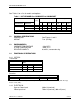
OPTELECOM MODEL 9311 See Table 1 for a list of models and options. Table 1 - LIST OF MODELS vs. BANDWIDTH & LINK BUDGET Model TRANSMITTER 9311T-S-ST 9311T-H1-ST λ (nm) RECEIVER 9311R-S-ST 9311R-S-ST 850 865 BW (MHz) vs. fiber length 2m 600m 160 180 9311R/HS-S-ST 865 150 9311T-LD-ST 9311R-L-ST 1310 220 * Depends on fiber distance x bandwidth product 1.2 1.3 1.4 Link budget 90 90 1.2 km 40 50 2.
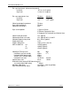
OPTELECOM MODEL 9311 Ext. sync input levels (referenced to ground) Low level - 0.7 to + 0.3 V, typical High level +1.0 to +4.3 V, typical Ext. sync output levels into; Low level High level 75 ohms 0V +2V 300 ohms 0V typical 3.2 V typical Video input/output impedance Sync input impedance Video/sync connectors 75 ohms 75 ohms BNC Sync source options 1) Sync-on-Green 2) External Composite Sync 3) Separate Ext.
OPTELECOM MODEL 9311 Table 2 - SYNC DELAY RELATIVE TO VIDEO Input Sync Output Sync Sync on Green Sync on Green Ext. comp. Sync Ext. comp. sync Ext. comp. Sync Ext. horiz. sync Ext. horiz. sync Ext. vert. sync Ext. vert. sync Delay relative to video +33 to +43 ns +90 to +110 ns +50 to +60 ns +90 to +110 ns H sync width +250 ns 1.4.3 POWER CONSUMPTION 9311T /MM 9311T/SM 6VDC @ 1.0 Amps 6VDC @ 1.25 Amps 9311R/MM 9311R/SM 6VDC @ 1.35 Amps 6VDC @ 1.5 Amps 1.4.4 COMPLIANCES UM50230, Rev.
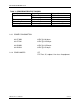
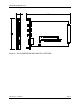
OPTELECOM MODEL 9311 Figure 1 – 9311T DIMENSIONS AND SWITCH LOCATIONS (S and L Versions Shown) UM50230, Rev.
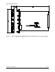
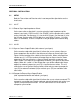
OPTELECOM MODEL 9311 Figure 2 – 9311R DIMENSIONS AND SWITCH LOCATIONS UM50230, Rev.
OPTELECOM MODEL 9311 SECTION 2 - INSTALLATION 2.1 SETUP Both the Transmitter and Receiver units have two-position dipswitches on the circuit card. 2.1.1 9311T 2.1.1.1External Sync Input Impedance Select On the transmitter, a dipswitch is used to select the input impedance of the external sync inputs, HS/CS and VS. See FIGURE 1 for the location of the switch on the circuit card. Position one (1) is for the HS/CS input. Position two (2) is for the VS input.
OPTELECOM MODEL 9311 2.2 MOUNTING To install the Model 9311T or 9311R, plug it into the card chassis In mounting the chassis itself, make sure there is enough space to connect both the electrical and optical cables to the panel without stressing them beyond the manufacturer’s limitations (bend radius minimums). 2.
OPTELECOM MODEL 9311 USER'S MANUAL 2.5 ELECTRICAL CABLING The Video and Sync connections are made via the HD15 Female connectors on the front panels of the 9311T and 9311R. 2.5.1 Model 9311T Transmitter If the video source is a personal computer, the video/sync connection from the computer to the 9311T is most likely made using a standard pin for pin VGA extension cable with a male HD15 connector on one end and a female HD15 connection on the other.
OPTELECOM MODEL 9311 USER'S MANUAL SECTION 3 - OPERATION 3.1 TURN-ON PROCEDURE To operate the units, connect the AC power cords and turn on the power switches on the power supplies (if applicable). Confirm that the indicator lights come on. 3.2 CONFIRMATION OF PROPER OPERATION If operating properly, the green “SYNC” indicator on the transmitter and all three “LVL” indicators on the receivers will be illuminated Green. Good video transmission will also be in evidence.
OPTELECOM MODEL 9311 USER'S MANUAL 3.5 TROUBLESHOOTING PROCEDURES If improper operation is evident, refer to the chart below. Consult the factory if you are unable to correct the problem. PROBLEM SYNC indicator on the 9311T is not illuminated (NOT SYNC indicator is illuminated) No video LVL indicators on the 9311R are illuminated. One or two video LVL indicators not illuminated but at least one is green. UM50230, Rev.
OPTELECOM MODEL 9311 USER'S MANUAL SECTION 4 – NETWORK SOFTWARE MANAGEMENT SYSTEM The following status and control is supported: DIGITAL STATUS BITS 9311T 1) Sync Present at Input 2) External Composite or Horizontal Sync Present at Input 3) External Vertical Sync Present at Input 9311R 1) Red Optical Input Power within AGC Range 2) Green Optical Input Power within AGC Range 3) Blue Optical Input Power within AGC Range ANALOG STATUS SIGNALS There are no analog status signals available to the Network Softwar