
Instruction manual

9
1
PANEL DESCRIPTION
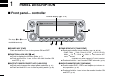
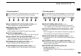
■ Main unit
qCONTROLLER CONNECTOR [CONTROLLER] (p. III)
Connects the controller unit with the supplied controller or
separation cable.
wDATA JACK [DATA]
(p. 57)
Connect to a PC via the optional data communication cable
OPC-1529R for data cloning with the optional cloning soft-
ware, CS-2820, or low-speed data communication in DV*
mode operation.
*Available only when the optional UT-123 is installed.
eGPS ANTENNA CONNECTOR [GPS ANT] (p. IV)
When the optional digital unit, UT-123, is installed, con-
nects the GPS antenna supplied with the optional UT-123.
rPACKET JACK [PACKET]
(pgs. 118, 119)
Connects a TNC (Terminal Node Controller), etc. for data
communications. The transceiver can support 1200/9600
bps packet communication
(AFSK/GMSK).
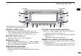
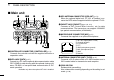
tMICROPHONE CONNECTOR [MIC]
(p. III)
Connects the supplied or an optional microphone.
q +8 V DC output (Max. 10 mA)
w Channel up/down
e 8V control IN
r PTT
t GND (microphone ground)
y MIC (microphone input)
u GND
i Data IN
yANTENNA CONNECTOR [ANT1 TX/RX] (p. IX)
Connects a 50 Ω antenna with a PL-259 connector and a
50 Ω coaxial cable for transmission and reception.
uCOOLING FAN
Rotates while transmitting.
Also rotates while receiving depending on the setting in set
mode.
(p. 99)
q
i
qwr te
!1
uio!0y