
Instruction manual

4
1
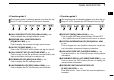
PANEL DESCRIPTION
1
2
3
4
5
6
7
8
9
10
11
12
13
14
15
16
17
18
19
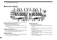
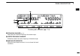
➥ During DV* (Digital) mode operation:
●
●
“DSQL” appears while the digital call sign squelch
function is in use.
(p. 90)
●
●
“CSQL” appears while the digital code squelch func-
tion is in use.
(p. 90)
➥ “” appears with the “TSQL,” “DTCS,” “DSQL”* or “C
SQL”* indicator while the pocket beep function is in use.
(pgs. 85, 90)
*Available only when the optional UT-123 is installed.
tEMR MODE INDICATOR (p. 56)
➥ “EMR” appears when the EMR mode* operation is in
use.
➥ “L” appears when packet loss occurs during the low-
speed data communication*.
*Available only when the optional UT-123 is installed.
yGPS INDICATOR (p. 122)
➥ Appears while GPS function* is in use and GPS signal
is received..
➥ Blinks when GPS signal cannot be received.
*Available only when the optional UT-123 is installed.
uDTMF INDICATOR (p. 82)
Appears while automatic DTMF transmission is in use.
iBREAK-IN INDICATOR
(p. 51)
Appears when the break-in* operation is in use.
*Available only when the optional UT-123 is installed.
oAUTO POWER OFF INDICATOR (p. 118)
Appears when the auto power OFF function is in use.
!0KEY LOCK INDICATOR
(p. 19)
Appears when the key lock function is activated.
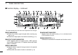
!1FREQUENCY READOUT
Shows the operating frequency, set mode contents, etc.
• Frequency decimal point blinks while scanning. (p. 74)
!2PRIORITY INDICATOR (p. 80)
Appears while priority watch is activated, blinks while pri-
ority watch is paused.
!3MEMORY CHANNEL NUMBER INDICATORS
➥ Shows the selected memory channel number.
(p. 60)
➥ Shows the selected bank initial. (p. 63)
➥ “C” appears when the call channel is selected. (p. 71)
!4SKIP INDICATOR (p. 78)
➥ “≈” appears when the displayed memory channel is
specified as a skip channel.
➥ “
P
≈” appears when the displayed frequency is specified
as a program skip frequency.
!5MEMORY INDICATOR
(p. 60)
Appears when memory mode is selected.