
Instruction manual
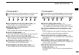

2
1
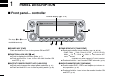
PANEL DESCRIPTION
1
2
3
4
5
6
7
8
9
10
11
12
13
14
15
16
17
18
19
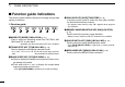
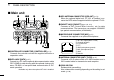
ySQUELCH CONTROL [SQL]
Varies the squelch level for left and right band.
(p. 20)
• The RF attenuator activates and increases the attenuation when
rotated clockwise at and beyond the center position. (p. 22)
uVOLUME CONTROL [VOL] (p. 20)
Adjusts the audio level for left or right band.
iTUNING DIAL [DIAL]
Selects the operating frequency
(p. 17), memory channel
(p. 60), the setting of the set mode item and the scanning
direction
(p. 75) for left or right band.
oMAIN•BAND KEY [MAIN•BAND]
➥ Push to select the main band.
(p. 15)
➥ Push and hold for 1 sec. to enter band selection mode.
(p. 15)
!0VFO/MHz TUNING•SCAN KEY [V/MHz•SCAN]
➥ Push to select between VFO mode and 1 MHz
(or
10 MHz for some versions) tuning. (p. 17)
➥ Push and hold for 1 sec. to enter scan type selection
mode.
(p. 74)
• Cancels a scan when pushed during scan.
!1
MEMORY/CALL•MEMORY WRITE KEY [M/CALL•MW]
➥ Push to select and toggle memory and call channel
modes.
(pgs. 60, 71)
➥ Push and hold for 1 sec. to enter select memory write
mode for memory channel programming.
(pgs. 61, 72, 75)
DUP
MONI
TONE
DTMF
LOW
PRIO
M/CALL
MW
V/MHz
SCAN
V/MHz
SCAN
M/CALL
MW
M
A
N
B
A
N
D
M
A
I
N
B
A
N
D
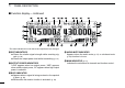
DUAL BAND TRANSCEIVER
iE2820
Left band Right band
y
u
i
y
u
i
oo!0 !0!1 !1
*The same controls for both the left and
right bands are arranged symmetrically.