INSTRUCTION MANUAL DUAL BAND FM TRANSCEIVER iE2820 This device complies with Part 15 of the FCC Rules. Operation is subject to the following two conditions: (1) this device may not cause harmful interference, and (2) this device must accept any interference received, including interference that may cause undesired operation.
FOREWORD IMPORTANT Thank you for purchasing this Icom product. The IC-E2820 DUAL BAND FM TRANSCEIVER is designed and built with Icom’s superior technology and craftsmanship. With proper care, this product should provide you with years of trouble-free operation. READ ALL INSTRUCTIONS carefully and completely We want to take a couple of moments of your time to thank you for making your IC-E2820 your radio of choice, and hope you agree with Icom’s philosophy of “technology first.
PRECAUTIONS RWARNING RF EXPOSURE! This device emits Radio Frequency (RF) energy. Extreme caution should be observed when operating this device. If you have any questions regarding RF exposure and safety standards please refer to the Federal Communications Commission Office of Engineering and Technology’s report on Evaluating Compliance with FCC Guidelines for Human Radio frequency Electromagnetic Fields (OET Bulletin 65). NEVER let objects impede the operation of the cooling fan on the rear panel.
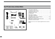
SUPPLIED ACCESSORIES q w u e r t i *HM-154 HAND MICROPHONE may be supplied with some versions. † Approx. y o iii q DC power cable (3 m) ………………………………………1 w Controller cable (10 cm†) ……………………………………1 e Separation cable (3.
TABLE OF CONTENTS FOREWORD .................................................................................... i IMPORTANT .................................................................................... i EXPLICIT DEFINITIONS .................................................................. i PRECAUTIONS ............................................................................... ii SUPPLIED ACCESSORIES ........................................................... iii TABLE OF CONTENTS .............
TABLE OF CONTENTS ■ Break-in communication ....................................................... 51 ■ Message operation ............................................................... 52 ■ Automatic reply function ........................................................ 55 ■ EMR communication ............................................................. 56 ■ Low-speed data communication ........................................... 57 ■ DV voice memory .......................................................
13 MENU SCREEN OPERATION ......................................... 95–112 ■ General ................................................................................. 95 ■ Menu list ................................................................................ 96 ■ Item list .................................................................................. 96 ■ SET MODE items .................................................................. 99 ■ DV SET MODE items ..........................................
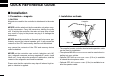
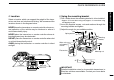
QUICK REFERENCE GUIDE ■ Installation D Precaution— magnets D Installation methods RCAUTION Magnets are used for the controller’s attachment to the main unit. Controller NEVER hold the whole unit by the controller only when carrying the transceiver. Carry the transceiver holding the main unit. If held by the controller, the main unit may drop off and may result in injury to the person carrying it or damage the transceiver.
D Location D Using the mounting bracket Select a location which can support the weight of the transceiver and does not interfere with driving. We recommend the locations shown in the diagram below. qDrill 4 holes where the mounting bracket is to be installed. NEVER place the transceiver or remote controller where normal operation of the vehicle may be hindered or where it could cause bodily injury. NEVER place the transceiver or remote controller where air bag deployment may be obstructed.
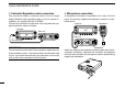
QUICK REFERENCE GUIDE D Controller/Separation cable connection D Microphone connection Two connection cables, controller cable (10 cm) for single body installation and separation cable (3.4 m) for remote installation, are supplied with the IC-E2820. A microphone connector is available on the main unit front panel. Connect the supplied microphone connector as illustrated below. Connect the controller and the main unit using with the supplied connection cable as follows.
D Optional GPS antenna connection D Important notes when using GPS receiver When the optional UT-123 is installed, the GPS antenna supplied with the UT-123 can be connected. Connect the GPS antenna as below. • The GPS antenna is not weather-proof construction, therefore, NEVER install the antenna in outdoor. GPS antenna to [GPS ANT] GPS antenna cable length: approx. 5 m (16.4 ft) Mount the GPS antenna onto a convenient flat surface.
QUICK REFERENCE GUIDE D Controller’s attachment D Remote installation You can attach the controller of the IC-E2820 by one of 2 methods. The supplied remote controller bracket is used for remote installation. • Attach the remote controller bracket onto a flat surface using with 4 self-tapping These screws screws (2.6 mm(d)), or doubleare not supplied. sticky tape, etc., as at left, then attach remote controller to the bracket.
wAttach the remote controller on to the optional MB-65 as below. Adjust the viewing angle for maximum visibility of the function display.
QUICK REFERENCE GUIDE D Battery connection ➥ RWARNING NEVER remove the fuse holders from the DC power cable. ➥ NEVER connect the transceiver directly to a 24 V battery. ➥ DO NOT use the cigarette lighter socket for power connections. (See p. 10 for details) Use a rubber grommet when passing the DC power cable through a metal plate to prevent a short circuit. • CONNECTING TO A DC POWER SOURCE Grommet IC-E2820 _ black ⊕ red + red RWARNING! NEVER remove the fuse holders.
D DC power supply connection Use a 13.8 V DC power supply with at least 15 A capacity. Make sure the ground terminal of the DC power supply is grounded. • CONNECTING TO A DC POWER SUPPLY Quick reference guide QUICK REFERENCE GUIDE IC-E2820 DC power supply 13.8 V to an AC outlet − − black ⊕ red ⊕ Fuses 20 A See p. 130 for fuse replacement.
QUICK REFERENCE GUIDE D Antenna installation • Antenna location To obtain maximum performance from the transceiver, select a high-quality antenna and mount it in a good location. It is not necessary to use radials on a magnetic mount (“mag mount”) antenna. Roof-mount antenna (Drill a hole or use a magnetic mount.) Trunk-mount antenna • Antenna connector The antenna uses a PL-259 connector.
■ Your first contact 2. Selecting the main band Now that you have your IC-E2820 installed in your car or shack, you are probably anxious to get on the air. We would like to take you through a few basic operation steps to make your first time “On The Air” an enjoyable experience. 1. Turning ON the transceiver Before powering up your IC-E2820, you may want to make sure the audio volume and squelch level controls are set in 9–10 o’clock positions.
QUICK REFERENCE GUIDE 3. Selecting the operating frequency band 4. Tune the frequency The IC-E2820 can use 2 m or 70 cm on either the left or right band. The operating band can be exchanged between them, and using the same bands, V/V and U/U, is also possible.. The tuning dial will allow you to dial in the frequency you want to use. Pages 17 and 18 will instruct you on how to set the tuning speed. [MAIN•BAND] [DIAL] Rotate the desired [DIAL].
■ Repeater operation 1. Setting duplex Using the HM-133 Push the desired band’s [MAIN•BAND] to select the main band. Push [DUP•MONI] once or twice to select minus duplex or plus duplex. Plus or minus duplex selection and the repeater tone setting can be made easily via the HM-133. Push [DUP– 7(TONE)] for minus duplex; [DUP+ 8(TSQLS)] for plus duplex selection, push [FUNC] then [DUP– 7(TONE)] to turn the repeater tone ON.
QUICK REFERENCE GUIDE ■ Programming memory channels The IC-E2820 has a total of 522 memory channels (including 20 scan edges and 2 call channels) for storing often used operating frequency, repeater settings, etc. Any memory channel can be recalled on either the left or right band. 1. Setting a frequency In VFO mode, set the desired operating frequency with repeater, tone and tuning steps, etc. ➥ Push the desired band’s [V/MHz•SCAN] to select VFO.
Using the HM-133 q Push [MR/CALL] to select memory mode. wPush [ENT C(T-OFF)] first, then enter the desired memory channel via the keypad. ePush [VFO/LOCK] to select VFO mode, then set the desired operating frequency, including offset direction, tone settings, etc. ➥ Push [VFO/LOCK] to select VFO. ➥ Push [ENT C(T-OFF)] first, then enter the desired operating frequency via the keypad.
1 PANEL DESCRIPTION ■ Front panel— controller Function display (pgs. 3–8) iE2820 DUAL BAND TRANSCEIVER q w D N N BAN BAN D MA *The keys w to t are for the MAIN band only. I MA V/MHz SCAN M/CALL MW DUP MONI TONE DTMF LOW PRIO t r e q POWER KEY [PWR] Push and hold for 1 sec. to turn power ON and OFF. w FUNCTION•LOCK KEY [F• ] ➥ Push to display the function guide. (p. 7) ➥ Push and hold for 1 sec. to turn the lock function ON and OFF. (p.
PANEL DESCRIPTION Left band Right band y y iE2820 DUAL BAND TRANSCEIVER u N N BAN BAN D *The same controls for both the left and right bands are arranged symmetrically. u D i MA MA o V/MHz SCAN M/CALL MW !0 !1 y SQUELCH CONTROL [SQL] Varies the squelch level for left and right band. (p. 20) • The RF attenuator activates and increases the attenuation when rotated clockwise at and beyond the center position. (p. 22) u VOLUME CONTROL [VOL] (p.
1 PANEL DESCRIPTION ■ Function display q w e r t y q u q w e r i o !0 @0 !1 !1 !2 !7 !9 !6 !5 !4 !2 !3 !8 !7 !6 !5 !4 !3 *The same indications for both the left and right bands are arranged. q OPERATING MODE INDICATOR (p. 21) Shows the selected operating mode. • FM, FM-N, AM, AM-N and DV* are available, depending on operating band. *Available only when the optional UT-123 is installed. w DUPLEX INDICATORS (p.
PANEL DESCRIPTION ➥ During DV* (Digital) mode operation: ● “DSQL” appears while the digital call sign squelch function is in use. (p. 90) ● “CSQL” appears while the digital code squelch function is in use. (p. 90) ➥ “ ” appears with the “TSQL,” “DTCS,” “DSQL”* or “C SQL”* indicator while the pocket beep function is in use. (pgs. 85, 90) *Available only when the optional UT-123 is installed. t EMR MODE INDICATOR (p. 56) ➥ “EMR” appears when the EMR mode* operation is in use.
1 PANEL DESCRIPTION ■ Function display— continued q w e r t y q u q w e r i o !0 @0 !1 !1 !2 !7 !9 !6 !5 !4 !2 !3 !8 !7 !6 !5 !4 !3 *The same indications for both the left and right bands are arranged. !6 S/RF INDICATORS ➥ Shows the relative signal strength while receiving signals. (p. 20) ➥ Shows the output power level while transmitting. (p.
PANEL DESCRIPTION @2 @3 @4 Function guide indications (pgs. 7, 8) @2 FREQUENCY MARKER (p. 27) Gap shows the selected frequency in the band scope. @3 CENTER FREQUENCY MARKER Dotted line shows the center frequency of the band scope. @4 BAND SCOPE INDICATOR When the band scope function is in use, shows the band conditions.
1 PANEL DESCRIPTION ■ Function guide indications The function guide indicators allow you to simply using a wide variety of functions. D Function guide q w r SCAN SKIP KEY [SKIP](TONE•DTMF) (p. 78) In memory mode, push to select the scan skip condition for the selected memory channel. • “≈” appears when memory skip, “P≈” appears when program skip selection. e r t y u tMEMORY NAME INDICATION KEY [M.N](LOW•PRIO) (p. 67) Push to select the memory name indication. q MODE KEY [MODE](V/MHz•SCAN) (p.
PANEL DESCRIPTION D Function guide 2 D Function guide 3 The function guide 2 indicators appear only when the optional UT-123 is installed and DV mode is selected. i o !0 1 !1 !2 !3 u i CALL SIGN SELECT KEY [CS](V/MHz•SCAN) (p. 38) Push to display the call sign selection screen. oRECEIVED CALL SIGN RECORD KEY [CD](M/CALL•MW) (p. 47) Push to display the received call sign record screen. !0 CQ KEY [CQ](DUP•MONI) (p. 39) Push to set “CQCQCQ” as the station call sign for the call.
1 PANEL DESCRIPTION ■ Main unit q we r t e GPS ANTENNA CONNECTOR [GPS ANT] (p. IV) When the optional digital unit, UT-123, is installed, connects the GPS antenna supplied with the optional UT-123. rPACKET JACK [PACKET] (pgs. 118, 119) Connects a TNC (Terminal Node Controller), etc. for data communications. The transceiver can support 1200/9600 bps packet communication (AFSK/GMSK). t MICROPHONE CONNECTOR [MIC] (p. III) Connects the supplied or an optional microphone.
PANEL DESCRIPTION i ANTENNA CONNECTOR [ANT2 RX] (p. IX) Connects a 50 Ω antenna with a PL-259 connector and a 50 Ω coaxial cable for diversity reception. o EXTERNAL SPEAKER JACK 1 [SP-1] Connects an 8 Ω speaker. Outputs audio from both left and right bands when no external speaker is connected to [SP2]. See the table at right for details. ANTENNA INFORMATION For radio communications, the antenna is of critical importance, to maximize your output power and receiver sensitivity.
1 PANEL DESCRIPTION ■ Microphone (HM-133*) q w e r r ACTIVITY INDICATOR ➥ Lights red while any key, except [FUNC] and [DTMF-S], is pushed, or while transmitting. ➥ Lights green while the one-touch PTT function is in use. Mic element t KEYPAD (pgs. 12, 13) t *A different microphone may be supplied depending on version. q VFO/LOCK KEY [VFO/LOCK] ➥ Push to select VFO mode. (p. 16) ➥ Push and hold for 1 sec. to turn the lock function ON and OFF. (p.
1 PANEL DESCRIPTION ■ Microphone keypad KEY FUNCTION SECONDARY FUNCTION ( +key) OTHER FUNCTIONS Switches between opening and closing the In VFO mode enters operating band selecsquelch. (p. 24) tion. In memory mode enters bank selection. (p. 63) Starts and stops scanning. (p. 74) Starts and stops tone scanning. Starts and stops priority watch. (p. 79) Turns the one-touch PTT function ON and OFF. (p. 26) Selects high output power. (p. 21) Turns the DTCS squelch ON. Selects mid. output power.
1 PANEL DESCRIPTION KEY FUNCTION SECONDARY FUNCTION ( +key) OTHER FUNCTIONS ➥ Cancels frequency entry. (p. 17) ➥ Stores the set frequency, etc., into the selected memory channel when pushed ➥ Cancels the scan or priority watch. and held. (pgs. 74, 80) (p. 62) ➥ Exit set mode. (p. 95) ➥ Advances the memory channel number when continuously pushed after programming is completed. (p. 62) ➥ Enters MENU screen. (p. 95) DTMF memory encoder function OFF. ➥ Enters selected set mode. (p. 95) (p.
PANEL DESCRIPTION ■ Optional Microphone (HM-154) w ON q e OFF q PTT SWITCH Push and hold to transmit; release to receive. w UP/DOWN KEYS [UP]/[DN] ➥ Push either key to change operating frequency, memory channel, set mode setting, etc. (pgs. 17, 60, 95) ➥ Push and hold either key for 1 sec. to start scanning. (p. 74) e UP/DN LOCK SWITCH Slide to toggle [UP]/[DN] keys function ON and OFF.
2 SETTING A FREQUENCY ■ Preparation D Turning power ON/OFF [PWR] D Operating frequency band selection In the default condition, or after resetting the CPU, 2 m band is assigned to the left band, 70 cm band is assigned to the right band. However, the 2 m band can also be assigned into the right, and 70 cm band can also be assigned into the left band. ➥ Push and hold [PWR] for 1 sec. to turn power ON and OFF.
SETTING A FREQUENCY BANK z Push [BAND] to select main band. x Push and hold [BAND] for 1 sec. to enter frequency band selection. • The frequency band is displayed. Y/Z c Push [Y]/[Z] to select the desired frequency band. v Push [CLR A(MW)] (or [BAND]) to exit the condition, and return to frequency indication.
2 SETTING A FREQUENCY ■ Using the tuning dial ■ Using the keypad q Rotate the desired band’s [DIAL] to set the frequency. The frequency can be directly set via numeral keys on the microphone. • If VFO mode is not selected, push the same band’s [V/MHz•SCAN] to select VFO mode. • The frequency changes in the selected tuning steps. (p. 18) ENT C z Push [BAND] to select the desired band (left or right) as the main band. • Push [VFO/LOCK] to select VFO mode, if necessary.
SETTING A FREQUENCY 2 ■ Tuning step selection Tuning steps are the minimum frequency change increments when you rotate [DIAL] or push [Y]/[Z] on the microphone. Independent tuning steps for the left and right bands, as well as each frequency band can be set for individual tuning convenience. The following tuning steps are available. • 5 kHz* • 15 kHz* • 50 kHz • 6.25 kHz* • 20 kHz • 10 kHz • 25 kHz • 12.5 kHz • 30 kHz *Not selectable in 900 MHz band.
2 SETTING A FREQUENCY ■ Lock functions To prevent accidental frequency changes and unnecessary function access, use the lock function. The transceiver has 2 different lock functions. D Frequency lock ] “ ” appears while the lock function is activated. ➥ Push and hold [F• ON and OFF. ] for 1 sec. to turn the lock function • [PTT], [DUP•MONI] (monitor function only), [VOL], [SQL] and [MAIN•BAND] (main band selection only) can be used while the channel lock function is in use.
BASIC OPERATION ■ Receiving 3 ■ Transmitting q Set the audio level for the main band. ➥ Push the desired band’s [MAIN•BAND]. ➥ Push and hold [DUP•MONI] for 1 sec. to open the squelch. ➥ Rotate the main band’s [VOL] to adjust the audio level. ➥ Push the [DUP•MONI] to close the squelch. w Set the squelch level. ➥ Rotate the main band’s [SQL] fully counterclockwise in advance, then rotate the [SQL] clockwise until the noise just disappears.
3 BASIC OPERATION ■ Selecting output power ■ Operating mode selection The transceiver has 3 output power levels to suit your operating requirements. Low output powers during short-distance communications may reduce the possibility of interference to other stations and will reduce current consumption. Operating modes are determined by the modulation of the radio signals. The transceiver has total 5 operating modes (FM, FM-N, AM, AM-N and DV* modes).
BASIC OPERATION 3 ■ Squelch attenuator The transceiver has an RF attenuator related to the squelch level setting. Approx. 10 dB attenuation is obtained at maximum setting. The squelch attenuator allows you to set the minimum signal level needed to open the squelch. The attenuator function can be deactivated in set mode. ➥ Rotate [SQL] clockwise past the 13 o’clock position to activate the squelch attenuator. • Attenuation level can be adjusted up to 10 dB (approx.
3 BASIC OPERATION ■ V/V, U/U simultaneous receive (Para-watch) The IC-E2820 can simultaneously receive two signals on the same band, such as 144 MHz band, using the para-watch function. Can be switched between VHF and UHF To activate the para-watch function from the HM-133, enter the desired frequencies for each the left and right bands using the direct frequency input capability via the keypad; or perform the following operation.
BASIC OPERATION 3 ■ Sub-band mute/busy beep ■ Monitor function The sub-band mute function automatically cuts out sub-band audio signals when both main and sub-band signals are received simultaneously. This function is used to listen to weak signals without disturbing the squelch setting. While operating on the main band, a beep sounds to inform you that a signal was received on the sub-band. q Push [F• ] to display the function guide. wPush [MENU](V/MHz•SCAN) (Right band’s) to enter MENU screen.
3 BASIC OPERATION ■ Single band operation D Single band/Dualwatch operation D Diversity operation Dualwatch operation monitors two frequencies simultaneously. The IC-E2820 has two independent receiver circuits: left band, and right band (available frequencies, operating mode and functions are different depending on bands). Single band operation is useful when only one frequency is being watched.
BASIC OPERATION 3 ■ One-touch PTT function When diversity operation is in use, connect the same type antenna to both [ANT1] and [ANT2 RX]. ➥ During single band operation with the diversity function ON, the diversity indicator appears as below. The PTT switch can be operated as a one-touch PTT switch (each push toggles between transmit/receive). Using this function you can transmit without pushing and holding the PTT switch.
3 BASIC OPERATION ■ Audio mute function ■ Band scope This function temporarily mutes the audio without disturbing the volume setting. (microphone only) The band scope function allows you to visually check a specified frequency range around the center frequency. ➥ Push [FUNC] then [SQLY D(MUTE)] to mute audio signals. About the sweep steps: The specified tuning step in each frequency band (in VFO mode) or programmed tuning step (in memory mode) is used during sweep. MUTE • The “ ” indicators appear.
BASIC OPERATION 3 D Single sweep D Monitoring a signal q Set the desired frequency as band scope center frequency. w Push [F• ] to display the function guide. ePush [SCP](DUP•MONI) to start a single sweep. If you find a signal that you want to monitor during/after sweep, you can monitor the signal with the following operation. qPush [F• ] to display the function guide, then push [SCP](DUP•MONI) to cancel the continuous sweep, if necessary. w Rotate [DIAL] to tune into the desired signal.
4 REPEATER OPERATION ■ General • Repeater operation flow chart Repeaters allow you to extend the operational range of your radio because a repeater has much higher output power than the typical transceiver. Step 1: Set the desired band to operate the repeater. Normally, a repeater has independent frequencies for each receiver and transmitter. A subaudible tone may also be required to access a repeater. Step 2: Set the desired receive frequency (repeater output frequency).
REPEATER OPERATION 4 ■ Accessing a repeater qSet the receive frequency (repeater output frequency) on the main band. (pgs. 15–17) wPush [DUP•MONI] one or two times, to select minus duplex or plus duplex. • “DUP–” or “DUP+” appears to indicate the transmit frequency for minus shift or plus shift, respectively. • When the auto repeater function is turned ON (available for the USA version only), steps w and e are not necessary. (p. 35) r Push and hold [PTT] to transmit.
4 REPEATER OPERATION DUP– 7 DUP+ 8 z Set the receive frequency (repeater output frequency) on the main band. (pgs. 16, 17) x Push [DUP– 7(TONE)] to select minus duplex; push [DUP+ 8(TSQLS)] to select plus duplex. • “DUP–” or “DUP+” appears. Push Push c Push [FUNC] then [DUP– 7(TONE)] to turn ON the subaudible tone encoder according to repeater requirements. • Refer to p. 32 for the tone frequency setting. • When the repeater requires a different tone system, see p. 33. Push then , .
REPEATER OPERATION 4 ■ Subaudible tones (Encoder function) D Subaudible tones qSelect the main band, mode/channel you wish to set the subaudible tones to, such as VFO mode or memory/call channel. w Push [F• ] to display the function guide. ePush [MENU](V/MHz•SCAN) (Right band’s) to enter MENU screen. rRotate [DIAL] to select “DUP/TONE…” then push [MAIN•BAND]. tRotate [DIAL] to select “REPEATER TONE” then push [MAIN•BAND].
4 REPEATER OPERATION D 1750 Hz tone D DTMF tones ➥ Push [DTMF-S], then push the keys of the deDTMF-S sired DTMF digits. • The function indicator lights green. • 0–9, A–D, ✱(E) and #(F) are available. • When “1” is displayed, cancel the DTMF memory encoder in advance. (p. 82) • Push [DTMF-S] again to return the keypad to normal function control. Push , The microphone has 1750 Hz tone capability, used for ring tone when calling, etc. z Push [FUNC]. TONE-1 • The function indicator lights orange.
REPEATER OPERATION 4 ■ Offset frequency When communicating through a repeater, the transmit frequency is shifted from the receive frequency by an amount determined by the offset frequency. Independent offset frequencies can be set for each operating frequency band. qPush [MAIN•BAND] to select the desired band (left or right) as the main band. wSelect the desired mode/channel you wish to set the offset frequency for, such as VFO mode or memory/call channel.
5 35 DV MODE OPERATION (Optional UT-123 is required) ■ Digital mode operation ■ Call sign programming The IC-E2820 can be operated in digital voice mode and lowspeed data operation for both transmit and receive when the optional UT-123 is installed. Also, position data transmission and reception are available with the UT-123. A GPS antenna is supplied with the UT-123.
DV MODE OPERATION (Optional UT-123 is required) 5 D Your own call sign programming Your own call sign must be programmed for both digital voice and low-speed data communications (including GPS transmission). q Push [F• ] to display the function guide. wPush [MENU](V/MHz•SCAN) (Right band’s) to enter MENU screen. eRotate [DIAL] to select “CALL SIGN MEMORY” then push [MAIN•BAND]. rRotate [DIAL] to select “MY CALL SIGN MEMORY” then push [MAIN•BAND].
5 DV MODE OPERATION (Optional UT-123 is required) D Station call sign programming Station call signs must be programmed for the specified station call as well as repeater operation in all digital voice, lowspeed data and GPS communications. q Push [F• ] to display the function guide. wPush [MENU](V/MHz•SCAN) (Right band’s) to enter MENU screen. eRotate [DIAL] to select “CALL SIGN MEMORY” then push [MAIN•BAND]. rRotate [DIAL] to select “YOUR CALL SIGN MEMORY” then push [MAIN•BAND].
DV MODE OPERATION (Optional UT-123 is required) 5 ■ Digital voice mode operation qSet the desired band (Left or Right) as the main band. (p. 15) • Select output power, if desired. (p. 21) w Select DV mode. (p. 21) e Set your own call sign for DV operation as follows. z Push [F• ] twice to display the function guide 2. xPush [CS](V/MHz•SCAN) (Left band’s) to display call sign screen. cRotate [DIAL] to select “MY” then push [MAIN•BAND].
5 DV MODE OPERATION (Optional UT-123 is required) D When calling the desired station Continued instruction from step v on page 38. bRotate [DIAL] to select “YOUR,” then push [MAIN•BAND]. • YOUR CALL SIGN screen is displayed. nRotate [DIAL] to select the call sign channel in which desired station’s call sign is programmed. • See page 38 for station call sign programming details. mPush [BACK](V/MHz•SCAN) (Right band’s) to set the station’s call sign and return to CALL SIGN screen.
DV MODE OPERATION (Optional UT-123 is required) 5 ■ DV automatic detect The “DV” mode indicator blinks when a non-DV signal is received during DV mode operation. The IC-E2820 DV automatic detection monitors in FM mode when other than DV mode signal is received. qPush [F• ] to display the function guide. wPush [MENU](V/MHz•SCAN) (Right band’s) to display the MENU screen. eRotate [DIAL] to select “DV SET MODE” then push [MAIN•BAND]. rRotate [DIAL] to select “DV AUTO DETECT” then push [MAIN•BAND].
5 DV MODE OPERATION (Optional UT-123 is required) ■ About D-STAR system In the D-STAR system, repeater linking via a 10 GHz band backbone and internet network (gateway connection) capabilities are available. This system provides you with much wider coverage range during digital voice mode operation. • D-STAR system outline Repeater A Also, the D-STAR system repeaters are connectable through the INTERNET— gateway connection capability.
DV MODE OPERATION (Optional UT-123 is required) 5 ■ Digital repeater operation Repeater call signs must be programmed for repeater operation in both digital voice and low-speed data communications. D Repeater call sign programming q Push [F• ] to display the function guide. wPush [MENU](V/MHz•SCAN) (Right band’s) to enter MENU screen. eRotate [DIAL] to select “CALL SIGN MEMORY” then push [MAIN•BAND]. rRotate [DIAL] to select “RPT CALL SIGN MEMORY” then push [MAIN•BAND].
5 DV MODE OPERATION (Optional UT-123 is required) D Repeater operation in the same zone qSet the desired repeater’s frequency, offset and shift direction in the main band. (pgs. 30, 31) • Select DV mode in advance. (p. 21) w Set your own call sign. (p. 38) • See p. 36 for your own call sign programming. e Set the desired station call sign. (p. 39) • See p. 38 for station call sign programming. r Set the repeater’s call sign as follows; z Push [F• ] twice to display the function guide 2.
DV MODE OPERATION (Optional UT-123 is required) 5 • Setting example 1 Zone Area 1 Repeater 1 : A11111 Area 2 Repeater 2 : A22222 Station A : A2222A ✔ What is the area? The Area is the communication range that is covered by a local repeater. The Local repeater is called an area repeater in the D-STAR system.
5 DV MODE OPERATION (Optional UT-123 is required) D Repeater operation into another zone qSet the desired repeater’s frequency, offset and shift direction in the main band. (pgs. 30, 31) • Select DV mode in advance. (p. 21) w Set your own call sign. (p. 38) • See p. 36 for your own call sign programming. e Set the desired station call sign. (p. 39) • When making a CQ call Set the desired repeater’s (in a different zone) call sign into “YOUR.
DV MODE OPERATION (Optional UT-123 is required) 5 • Setting examle 2 Zone A Area 1 Repeater 1 : A11111 Area 2 Repeater 2 : A22222 Station A : A2222A Area 3 (Gateway) Repeater 3 : A33333 Internet network Area 4 Repeater 4 : A44444 Area 8 Repeater 8 : B88888 Station B : A3333B Zone B Area 5 Repeater 5 : B55555 Area 6 Repeater 6 : B66666 Area 7 (Gateway) Repeater 7 : B77777 Station C : B6666C ❑ The setting when Station A is calling Station C UR : B6666C R1 : A22222 R2 : A33333 G MY : A2
5 DV MODE OPERATION (Optional UT-123 is required) ■ Received call sign When a call is received in DV mode, the calling station and the repeater call signs being used can be stored into the received call record. The stored call signs are viewable in the following manner. Up to 20 calls can be recorded. ePush [MAIN•BAND] to display the received call details. • CALLER • CALLED • RXRPT1 • RXRPT2 : The station call sign that made a call. : The station call sign called by the caller.
DV MODE OPERATION (Optional UT-123 is required) 5 D One-touch reply qAfter receiving a call, push [F• ] twice to display the function guide 2. wPush [R>CS](TONE•DTMF) to set the received call sign as for the call. [R>CS] D One-touch reply using the call record The stored call signs in the call record can be used to the call. qPerform the steps q and w of “D Desired call record indication” described on the previous page.
5 DV MODE OPERATION (Optional UT-123 is required) ■ Copying the call sign D Copying the call sign memory contents This function is convenient when modifying part of the current call sign. NOTE: Make sure that the “EDIT RECORD” item in DV set mode is set to “AUTO” in advance. (p. 102) q Push [F• ] twice to display the function guide 2. wPush [CS](V/MHz•SCAN) (Left band’s) to display the “CALL SIGN” screen. eRotate [DIAL] to select “YOUR” or “RPT1/2” then push [MAIN•BAND].
DV MODE OPERATION (Optional UT-123 is required) D Copying the call record contents into call sign memory This is a way to copy the call record contents (“CALLER,” “RXRPT1” and “RXRPT2”) into call sign memory (“YOUR” and “RPT”) at the same time or individually. q Push [F• ] to display the function guide. wPush [MENU](V/MHz•SCAN) (Right band’s) to display the “MENU” screen. eRotate [DIAL] to select “RX CALL SIGN,” then push [MAIN•BAND].
5 DV MODE OPERATION (Optional UT-123 is required) ■ Break-in communication The break-in function allows you to break into a conversation, where the two original stations are communicating with call sign squelch enabled. qWhile receiving an another station’s communication, push [F• ] twice to display the function guide 2 and then push [R>CS](TONE•DUP) to set the communicating station’s call sign. • When a call sign has not been received correctly, error beeps sound and no call sign is set.
DV MODE OPERATION (Optional UT-123 is required) 5 ■ Message operation D TX message programming TX messages are available for up to 5 channels, and each channel can be programmed with a message of up to 20 characters. Available characters are 0 to 9, A to Z (capital letters), a to z (lower case letters), some symbols and space. q Push [F• ] to display the function guide. wPush [MENU](V/MHz•SCAN) (Right band’s) to display the “MENU” screen. eRotate [DIAL] to select “DV MESSAGE,” then push [MAIN•BAND].
5 DV MODE OPERATION (Optional UT-123 is required) D Message Transmission Select the message transmission function ON (Ch01–05) and OFF. When a message channel is selected, the transceiver transmits a text message (pre-programmed). (default: OFF) q Push [F• ] twice to display the function guide 2. wPush [MSG](LOW•PRIO) to display the “MESSAGE” screen. eRotate [DIAL] to select “TX MESSAGE,” then push [MAIN•BAND]. r Rotate [DIAL] to select the desired message channel. • “Ch01” to “Ch05” available.
DV MODE OPERATION (Optional UT-123 is required) 5 D RX message indication The received message can also be checked via MENU screen and function guide 2. ➥ Via MENU screen q Push [F• ] to display the function guide. wPush [MENU](V/MHz•SCAN) (Right band’s) to display the “MENU” screen. eRotate [DIAL] to select “DV MESSAGE,” then push [MAIN•BAND]. rRotate [DIAL] to select “RX MESSAGE,” then push [MAIN•BAND]. ➥ Via function guide 2 q Push [F• ] twice to display the function guide 2.
5 DV MODE OPERATION (Optional UT-123 is required) ■ Automatic reply function The automatic reply function replies to calls by a station that specified your call sign. Two methods of replying are available: one is making a reply call with your own call sign, and other one is making a reply call with reply voice audio that has been recorded in DV voice memory. D Automatic reply function setting q Push [F• ] to display the function guide. wPush [MENU](V/MHz•SCAN) (Right band’s) to display the “MENU” screen.
DV MODE OPERATION (Optional UT-123 is required) D Play-back or erase the voice memory q Push [F• ] to display the function guide. wPush [MENU](V/MHz•SCAN) (Right band’s) to display the “MENU” screen. eRotate [DIAL] to select “DV VOICE MEMO,” then push [MAIN•BAND]. rRotate [DIAL] to select “REPLY VOICE,” then push [MAIN•BAND]. tTo play-back the recorded reply voice, push [≈](LOW•PRIO). • Push [||](LOW•PRIO) to pause, push [■](TONE•DUP) to cancel the play-back.
5 DV MODE OPERATION (Optional UT-123 is required) ■ Low-speed data communication In addition to the digital voice communication, low-speed data communication is available. The optional OPC-1529R DATA COMMUNICATION CABLE and serial data communication software (purchase locally) are required in addition. NOTE: Turn OFF the GPS data communication (p. 127) in advance to operate the low-speed data communication.
DV MODE OPERATION (Optional UT-123 is required) 5 ■ DV voice memory D Transmission condition setting q Push [F• ] to display the function guide. wPush [MENU](V/MHz•SCAN) (Right band’s) to display the “MENU” screen. eRotate [DIAL] to select “DV SET MODE,” then push [MAIN•BAND]. rRotate [DIAL] to select “DV DATA TX,” then push [MAIN•BAND]. t Rotate [DIAL] to select the desired transmission condition. PTT : The entered text data in the Terminal Window (buffer screen) is transmitted when [PTT] is pushed.
5 DV MODE OPERATION (Optional UT-123 is required) ◆ Track size setting The track size can be changed with the following instruction. qPush [F• ] to display the function guide. wPush [MENU](V/MHz•SCAN) (Right band’s) to display the MENU screen. eRotate [DIAL] to select “DV VOICE MEMO” then push [MAIN•BAND]. rRotate [DIAL] to select “TRACK SIZE” then push [MAIN•BAND]. tRotate [DIAL] to select the desired track size. 10SEC/3TRACK : Makes 3 tracks and 10 seconds audio can be recorded in each track.
MEMORY MODE OPERATION 6 ■ General description The transceiver has 522 memory channels, including 20 scan edge memory channels (10-pairs) and 2 call channels. Each of these channels can be individually programmed with operating frequency (pgs. 15–17), duplex direction (p. 30) and offset (p. 34), subaudible tone encoder or tone squelch and its tone frequency (pgs. 32, 85–87) and skip information (p. 78). In addition, a total of 26 memory banks, A to Z, are available for usage by group, etc.
6 MEMORY MODE OPERATION ■ Programming a memory channel VFO settings, including MENU group contents such as subaudible tone frequency and offset can be programmed into a memory channel. qSet the desired frequency in the desired band (left or right). ➥ Push the desired band’s [V/MHz•SCAN] to select VFO mode. ➥ Set the frequency using the same band’s [DIAL]. ➥ Set other data (e.g. tone frequency, duplex information, etc.) if required. w Push and hold the same band’s [M/CALL•MW] for 1 sec.
MEMORY MODE OPERATION 6 D Programming a memory channel via the microphone The microphone can also be used to program memMW ory channels. z Set the desired frequency in VFO mode. ➥ Push [VFO/LOCK] to select VFO mode. ➥ Set the frequency using the keypad. ➥ Set other data (e.g. offset frequency, duplex direction, subaudible tone encoder ON/OFF and its frequency), if necessary. x Push [MR/CALL] to enter memory mode. c Push [ENT C(T-OFF)], then set the desired memory channel using the keypad.
6 MEMORY MODE OPERATION ■ Memory bank selection The IC-E2820 has a total of 26 banks (A to Z). All memory channels, regular channels, scan edges and call channels are assigned into the desired bank for easy memory management. qPush the desired band’s [M/CALL•MW] several times to select memory mode, if desired. wPush and hold the same band’s [MAIN•BAND] for 1 sec. eRotate the same band’s [DIAL] to select the desired bank, A to Z. • Banks that have no programmed contents are skipped.
MEMORY MODE OPERATION 6 ■ Memory bank setting qPush the desired band’s [M/CALL•MW] several times to select memory mode, then rotate the same band’s [DIAL] to select the desired memory channel. wPush and hold the same band’s [M/CALL•MW] for 1 sec. • “X” and memory number indication blinks. ePush [SEL](V/MHz•SCAN) (Left band’s) once to select “BANK” setting stand-by condition. • “X” indicator blinks. r Push [EDIT](M/CALL•MW) (Right band’s) to edit. • “X” and 1st digit blink.
6 MEMORY MODE OPERATION ■ Programming memory/bank/scan name Each memory channel can be programmed with an alphanumeric channel name for easy recognition and can be indicated independently by channel. Names can be a maximum of 8 characters— see the following table for available characters. q Select the desired memory channel to be programmed. ➥ Push [M/CALL•MW] several times to select memory mode, then rotate the same band’s [DIAL] to select the desired memory channel.
MEMORY MODE OPERATION 6 [EXAMPLE]: Programming the bank name “AIR” into the scan edge channel 3A. SEL Memory mode Push M/CALL MW V/MHz (Main band’s) to select memory mode. Push SCAN (Main band’s) several times to select “B NAME”. EDIT IN B A (Main band’s) to select scan edge Push (Right band’s) to enter bank name edit mode. Bank name edit mode M Rotate A IN B A (Main band’s) to > M/CALL Push and hold MW (Main band’s) for 1 sec. to enter select memory write condition.
6 MEMORY MODE OPERATION ■ Copying memory contents This function copies a memory channel’s contents to VFO (or another memory/call channel). This is useful when searching for signals around a memory channel frequency and for recalling the offset frequency, subaudible tone frequency etc. MR/CALL D Memory/call➪VFO qSelect the desired band’s (left or right) memory or call channel.
MEMORY MODE OPERATION D Memory/call➪call/memory q Select the memory/call channel to be copied. ➥ Push the desired band’s [M/CALL•MW] several times to select memory mode or call channel, then rotate the same band’s [DIAL] to select the desired memory or call channel. w Push and hold the same band’s [M/CALL•MW] for 1 sec. • “X” indicator and the memory channel number blink. eRotate the same band’s [DIAL] to select the target memory channel. • “C1” or “C2” blinks when the call channel is selected.
6 MEMORY MODE OPERATION ■ Memory clearing Contents of programmed memories can be cleared (blanked), if desired. qPush [V/MHz•SCAN] to select VFO mode in the desired band (left or right). wPush and hold the same band’s [M/CALL•MW] for 1 sec. • “X” indicator and the memory channel number blink. eRotate [DIAL] to select the memory channel to be cleared. r Push and hold [CLR](DUP•MONI) for 1 sec. to clear. tPush [BACK](V/MHz•SCAN) (Right band’s) to return to VFO mode.
MEMORY MODE OPERATION 6 ■ Erasing/transferring bank contents Contents of programmed memory banks can be cleared or transferred to another bank. INFORMATION: Even if the memory bank contents are cleared, the memory channel contents still remain programmed. qSelect the desired bank contents to be transferred or erased from the band (left or right). ➥ Push the desired band’s [M/CALL•MW] several times to select memory mode. ➥ Push and hold the same band’s [MAIN•BAND] for 1 sec.
7 CALL CHANNEL OPERATION ■ Call channel selection ■ Call channel copying Call channel is a pre-programmed memory channel that can be accessed by simply pushing call channel button. D Call➪VFO/Memory ➥ Push the desired band’s [M/CALL•MW] several times to select the call channel mode, then rotate the same band’s [DIAL] to select the desired call channel. • “C0” or “C1” appears instead of memory channel number.
CALL CHANNEL OPERATION 7 ■ Programming a call channel Operating frequency, duplex information, subaudible tone information (tone encoder or tone squelch ON/OFF and its frequency) can be programmed into the call channel. q Set the desired frequency in VFO mode. ➥ Push the desired band’s [V/MHz•SCAN] to select VFO mode. ➥ Set the frequency using the same band’s [DIAL]. ➥ Set other data as desired. w Push and hold the same band’s [M/CALL•MW] for 1 sec.
8 SCAN OPERATION ■ Scan types Scanning searches for signals automatically and makes it easier to locate new stations for contact or listening purposes. FULL SCAN (p. 74) 118.000 MHz 549.995* MHz Jump *depends on left or right band. PROGRAMMED SCAN (p. 74) Scan edges xxA Band xxB edge Scan Jump Band edge Band edge Scan 73 Jump (p. 74) Repeatedly scans between two user-programmed frequencies. Used for checking for frequencies within a specified range such as repeater output frequencies, etc.
SCAN OPERATION 8 ■ Scan start/stop D Preparation Scan resume condition (p. 77); program the scan edges (pgs. 75, 76); program 2 or more memory channels (pgs. 61, 62); set skip settings, if desired (p. 78). D Operation qSelect VFO mode for full/programmed scan with [V/MHz•SCAN]; or memory mode for memory scan with [M/CALL•MW] in the desired band (Left or Right). • Select the desired bank with the same band’s [MAIN•BAND] for bank scan. w Push and hold the same band’s [V/MHz•SCAN] for 1 sec.
8 SCAN OPERATION ■ Scan edges programming rPush and hold [S.MW](M/CALL•MW) (Left band’s) for 1 sec. to program. Scan edges can be programmed in the same manner as memory channels. Scan edges are programmed into scan edges, 0A/0B to 9A/9B, in memory channels. • 3 beeps sound and VFO is automatically selected. • Scan edge 0B to 9B is automatically selected when continuing to push the [M/CALL•MW] after programming.
SCAN OPERATION 8 D Programming scan edges via microphone z Push [MR/CALL] to select memory mode. MW x Select scan edge channel, 0A to9A using [Y]/[Z] or keypad. • Push [ENT C(T-OFF)] then push only 1 appropriate digit key, [VOLY 0(TONE-2)] to [SIMP 9(16-KEY-L)] then M(TONE-1)] or [SQLZ #(16KEY-L)] to select scan push [M M” and “#” can be used for “A” and edge channels. “M “B” respectively. v Push [FUNC], then push and hold [CLR A(MW)] for 1 sec. to program.
8 SCAN OPERATION ■ Scan resume condition The scan resume condition can be selected as timer or pause scan. The selected resume condition is also used for priority watch. (p. 80) The display shows that the scan will resume 15 sec. after it stops. qPush [MAIN•BAND] to select the desired band (left or right) as the main band. w Push [F• ] to display the function guide. ePush [MENU](V/MHz•SCAN] (Right band’s) to enter MENU screen. rRotate the [DIAL] to select “SCAN,” then push [MAIN•BAND].
SCAN OPERATION ■ Skip channel setting The memory skip function speeds up scanning by checking only those memory channels not set as skip channels. Set skip channels as follows. Skip indicator appears q Select a memory channel in the desired band (Left or Right): ➥ Push the desired band’s [M/CALL•MW] to select memory mode. ➥ Rotate the same band’s [DIAL] to select the desired channel to be a skip channel. w Push [F• ] to display the function guide.
9 PRIORITY WATCH ■ Priority watch types Priority watch checks for signals on a VFO frequency every 5 sec. while operating in memory mode. The transceiver has 3 priority watch types to suit your needs. You can also transmit on the VFO frequency while the priority watch operates. The watch resumes according to the selected scan resume condition. See page 77 for details. NOTE: If the pocket beep function is activated, the transceiver automatically selects the tone squelch function when priority watch starts.
PRIORITY WATCH 9 ■ Priority watch operation qSelect VFO mode, then set an operating frequency in the desired MAIN band (left or right). w Set the watched channel(s). For memory channel watch: Select the desired memory channel. For memory scan watch: Select memory mode; then, push and hold the main band’s [V/MHz•SCAN] for 1 sec. to start memory scan. For call channel watch: Select the desired call channel by pushing the main band’s [M/CALL•MW] once or twice, then rotate the [DIAL].
10 DTMF MEMORY ENCODER ■ Programming a DTMF tone sequence DTMF tone sequences are used for autopatching, controlling other equipment, etc. The transceiver has 16 DTMF memory channels (d0–d#) for storage of often-used DTMF tone sequences of up to 24 digits. qPush and hold [TONE•DTMF] for 1 sec. wRotate [DIAL] to select the “DTMF MEMORY,” then push [MAIN•BAND]. eRotate [DIAL] to select the desired memory channel, then push [MAIN•BAND]. • A total of 16 channels, “d0” to “d#” are available.
DTMF MEMORY ENCODER 10 ■ Transmitting a DTMF tone sequence D Automatic transmission (DTMF memory) qPush and hold [TONE•DTMF] for 1 sec. to enter DTMF set mode. wRotate [DIAL] to select “DTMF MEMORY,” then push [MAIN•BAND] to enter DTMF memory screen. eRotate [DIAL] to select the desired DTMF memory channel to be transmitted then push [BACK](V/MHz•SCAN) (Right band’s). • Returns to DTMF set mode screen. rRotate [DIAL] to select “AUTO TX,” then push [MAIN•BAND].
10 DTMF MEMORY ENCODER D Transmitting a DTMF memory directly z Push [FUNC] then [LOW 6(DTMF)] to turn the DTMF-S DTMF memory encoder ON. • “☎” appears. x Push [DTMF-S] to turn the DTMF memory direct selection ON. • The function indicator (microphone) lights green. c Push the desired DTMF channel. • “0” to “9,” “A” to “D,” “✱” and “#” are available for DTMF memory channels. • The selected DTMF tone sequence is automatically transmitted without pushing PTT.
DTMF MEMORY ENCODER ■ DTMF speed The rate at which DTMF values in memory send individual DTMF characters can be set to accommodate operating needs. q Push [F• ] to display the function guide. wPush [MENU](V/MHz•SCAN) (Right band’s) to enter MENU screen. eRotate [DIAL] to select “DUP/TONE…,” then push [MAIN•BAND]. rRotate [DIAL] to select “DTMF SPEED,” then push [MAIN•BAND]. tRotate [DIAL] to select the desired speed as shown in the table below, then push [MAIN•BAND].
11 TONE SQUELCH AND POCKET BEEP ■ Tone/DTCS squelch beep operation qSet the desired operating frequency and the desired operating mode. wSet the desired CTCSS tone or DTCS code. ePush [TONE•DTMF] several times to select the desired squelch system • “T SQL ”: Tone squelch with pocket beep; “DTCS ”: DTCS squelch with pocket beep; “T SQL”: Tone squelch; “DTCS”: DTCS squelch rWhen a signal with the correct tone or code is received, the transceiver’s mute is released and received audio sounds.
TONE SQUELCH AND POCKET BEEP 11 D Reverse tone/DTCS squelch D Setting tone squelch frequency The reverse tone/DTCS squelch is convenient if you want to ignore a specific signal. q Push [F• ] to display the function guide. w Push [MENU](V/MHz•SCAN) (Right band’s) to enter MENU screen. e Rotate [DIAL] to select “DUP/TONE…” then push [MAIN•BAND]. r Rotate [DIAL] to select “CTCSS TONE” then push [MAIN•BAND]. t Rotate [DIAL] to select the desired CTCSS tone frequency then push [MAIN•BAND].
11 TONE SQUELCH AND POCKET BEEP D Setting DTCS code q Push [F• ] to display the function guide. w Push [MENU](V/MHz•SCAN) (Right band’s) to enter MENU screen. e Rotate [DIAL] to select “DUP/TONE…” then push [MAIN•BAND]. r Rotate [DIAL] to select “DTCS CODE” then push [MAIN•BAND]. t Rotate [DIAL] to select the desired DTCS code then push [MAIN•BAND]. • Each operating band and each memory channel have independent settings. • See the table at right for available DTCS code.
TONE SQUELCH AND POCKET BEEP 11 ■ DTCS polarity setting q Push [F• ] to display the function guide. w Push [MENU](V/MHz•SCAN) (Right band’s) to enter MENU screen. e Rotate [DIAL] to select “DUP/TONE…” then push [MAIN•BAND]. r Rotate [DIAL] to select “DTCS POLARITY” then push [MAIN•BAND]. t Rotate [DIAL] to select the desired DTCS polarity then push [MAIN•BAND]. • BOTH N : Normal phase is used for both TX and RX. (Default) • TN-RR : Normal phase is used for TX; Reverse phase for RX.
11 TONE SQUELCH AND POCKET BEEP ■ Tone scan By monitoring a signal that is being operated with pocket beep, tone or DTCS squelch function, you can determine the tone frequency or DTCS code necessary to open squelch. qPush [F• ] to display the function guide. w Push [MENU](V/MHz•SCAN) (Right band’s) to enter MENU screen. e Rotate [DIAL] to select “DUP/TONE…” then push [MAIN•BAND]. r Rotate [DIAL] to select either “REPEATER TONE,” “CTCSS TONE” or “DTCS CODE” to be scanned.
TONE SQUELCH AND POCKET BEEP ■ Digital call sign/digital code squelch NOTE: Use digital code squelch when operating with two or more stations. Because the digital call sign squelch function recognizes “MY CALL SIGN,” the digital call sign squelch function can be used when operating with only one station. q Set the desired operating frequency in DV mode, Digital code and MY CALL SIGN. w Push [TONE•DTMF] several times to activate the digital code or digital call sign squelch.
12 PAGER/CODE SQUELCH ■ Pager function ■ Code programming This function uses DTMF codes for paging and can be used as a “message pager” to confirm you of a caller’s identification even when you leave the transceiver temporarily unattended. Pager selective code (push [PTT]) Beep Beep Beep Answer back (manual) q Decide the ID code of each transceiver and a group code for your group. w Decide whether you want to return to normal operation or code squelch operation after a connection is made.
PAGER/CODE SQUELCH 12 D Code programming Your ID code MUST be programmed into code channel C0. Up to 5 transmit codes (codes that you transmit) are programmable into code channels, C1 to C5, if required. q Push [F• ] to display the function guide. w Push [MENU](V/MHz•SCAN) (Right band’s) to enter MENU screen. e Rotate [DIAL] to select “DUP/TONE…” then push [MAIN•BAND]. r Rotate [DIAL] to select “PGR MEMORY”, then push the [MAIN•BAND]. t Rotate [DIAL] to select code channel C0.
12 PAGER/CODE SQUELCH ■ Pager operation D Calling a specific station q Program the pager code channel in advance (p. 92). w Set the operating frequency. • Set the volume and squelch to the desired level as in normal operation. e Push [F• ] to display the function guide. r Push [MENU](V/MHz•SCAN) (Right band’s) to enter the MENU screen. t Rotate [DIAL] to select “DUP/TONE…” then push [MAIN•BAND] to enter DUP/TONE set mode. y Rotate [DIAL] to select the “PGR/C-SQL” then push [MAIN•BAND].
PAGER/CODE SQUELCH • PERSONAL CALLS This display appears when you are called with your ID code and the calling station’s ID code is 444. “PGR” blinks. • GROUP CALLS This display appears when you are called with the group code (444), provided 444 has been programmed into code channel C3. Code channel • ERROR INFORMATION When the transceiver receives an incomplete code, “E” and previously received code appear. Previously received code.
13 MENU SCREEN OPERATION ■ General MENU screen is used for programming infrequently changed values or conditions of functions. • Entering MENU screen and operation q Push [F• ] to display the function guide. w Push [MENU](V/MHz•SCAN) (Right band’s) to enter MENU screen. [MENU] e Rotate [DIAL] to select the desired menu group, then push [MAIN•BAND]. r Rotate [DIAL] to select the desired item, then push [MAIN•BAND]. t Rotate [DIAL] to select the desired condition or value, then push [MAIN•BAND].
MENU SCREEN OPERATION ■ Menu list ITEMS CALL SIGN MEMORY† ■ Items list REF. ITEMS REF. D CALL SIGN MEMORY† — DUP/TONE... p. 104 ITEMS REF. — DISPLAY p. 105 YOUR CALL SIGN MEMORY — DV MESSAGE† — SOUNDS p. 107 RPT CALL SIGN MEMORY — DV VOICE MEMO† — DV GPS p. 108 RX CALL SIGN† 13 SET MODE p. 99 PACKET p. 109 DV SET MODE p. 101 GPS SET MODE p. 109 SCAN p. 103 GPS-A SET MODE p. 111 †Refer to the chapter 5 for details. ITEMS MY CALL SIGN MEMORY REF.
13 MENU SCREEN OPERATION D SCAN D SET MODE ITEMS REF. ITEMS REF. REF. ITEMS REF. p. 99 AUTO ATT p. 100 SCAN TIMER p. 103 BANK LINK SCAN p. 103 AUTO POWER OFF p. 99 ALC p. 100 PROGRAM SKIP SCAN p. 103 BANK LINK p. 103 PTT LOCK p. 99 DIVERSITY p. 100 BUSY LOCKOUT p. 99 GPS p. 100 FAN CONTROL p. 99 HM-154 UP p. 100 SQL DELAY p. 100 HM-154 DN p. 100 MIC SENS LEVEL p. 100 D DV SET MODE ITEMS 97 ITEMS TIME-OUT TIMER REF. ITEMS D DUP/TONE… ITEMS REF. OFFSET FREQ p.
MENU SCREEN OPERATION D GPS-A SET MODE D SOUNDS ITEMS ITEMS REF. KEY-TOUCH BEEP p. 107 SUB BAND MUTE p. 107 BEEP LEVEL p. 107 SUB BAND BEEP p. 107 SCOPE AF OUTPUT p. 107 STANDBY BEEP p. 107 REF. D DV GPS ITEMS REF. ITEMS REF. GPS SENTENCE p. 108 GPS TX p. 108 GPS MESSAGE p. 108 GPS AUTO TX p. 108 RX GPS MESSAGE p. 108 D PACKET ITEMS PACKET BPS REF. ITEMS p. 109 PACKET BAND REF. p. 109 D GPS SET MODE ITEMS 13 REF. ITEMS REF. GPS SPEED p. 109 GPS DATUM p. 109 UNITS p.
13 MENU SCREEN OPERATION ■ SET MODE items D Time-out timer D PTT lock To prevent accidental prolonged transmission, etc., the transceiver has a time-out timer. This function cuts a transmission OFF after 3, 5, 15 or 30 min. of continuous transmission. This timer can be cancelled. • OFF : The time-out timer is turned OFF. Turns the PTT lock function ON and OFF (default). Transmission with [PTT] is inhibited when ON is selected to prevent accidental transmission, etc.
MENU SCREEN OPERATION D Squelch delay D Diversity Selects squelch delay from short and long to prevent repeated opening and closing of the squelch during reception of the same signal. • SHORT : Short squelch delay. (default) • LONG : Long squelch delay Turns the diversity function ON and OFF (default). 13 D GPS Turns the GPS function ON (default) and OFF. D Mic sens level D HM-154 UP/DN Selects the microphone sensitivity from HIGH (default) and LOW to suit your preference.
13 MENU SCREEN OPERATION ■ DV SET MODE items The following items are selectable by optional UT-123 is installed into the IC-E2820. D Auto reply This function replies to an individual station call even you are away from the transceiver. After a manual transmission (pushing [PTT]), the Auto Reply setting returns to OFF automatically. • OFF : No reply is performed even a call is received. (default) • ON • VOICE : Sets caller’s call sign and reply to the call with the set own call sign automatically.
MENU SCREEN OPERATION 13 D Repeater call sign auto write D Call sign edit record When accessing a repeater with a call sign that is different than the one programmed in your radio, the repeater call sign can be set into “RPT1” and or “RPT2” automatically by reading the repeater’s transmission. (default: OFF) Selects the call sign programming when the call sign is edited or corrected with the pre-programmed call sign via call sign set screen.
13 MENU SCREEN OPERATION ■ SCAN items D Scan timer D Bank link scan Selects scan resume timer from T-15 (default), T-10, T-5 and P-2. • T-15/10/5 : Scan pauses for 15/10/5 sec., then resumes. • P-2 : Pause on a signal until signal disappears, then resumes 2 sec. after the signal disappears. Sets the memory bank link function ON and OFF (default). The link function provides continuous bank scan, scanning all contents in the selected banks during bank scan.
MENU SCREEN OPERATION 13 ■ DUP/ TONE items D Offset frequency D DTCS code Sets the duplex offset frequency from 0 to 159.995 MHz. During duplex (repeater) operation, transmit frequency shifts the set frequency. (default value may differ depending on operating fre- Sets DTCS code (both encoder and decoder) for DTCS squelch operation. Total of 104 codes are available. (default: 023) quency band) • Push [MHz](V/MHz•SCAN) (Left band’s) to tune in 1 MHz steps.
13 MENU SCREEN OPERATION ■ DISPLAY items D PGR/C-SQL D Backlight Sets pager or code squelch function ON (“PGR” for pager function ON; “C-SQL” for code squelch function ON) and OFF. (default: OFF) Sets backlighting color conditions. The color can be changed between red and green in 20 steps. Red (Left edge) ↔ Yellow green (Center) ↔ Green (Right edge) (default: Center) D PGR MEMORY Sets code memory for pager and code squelch operation. (default: C0) See page 92 for code programming details.
MENU SCREEN OPERATION 13 D Opening logo D RX Call Sign Display The opening logo indication (Icom logo and transceiver name) that is displayed at power ON can be skipped, if desired. • ON : Opening logo is displayed at power ON. (default) • OFF : Opening logo indication is skipped. ☞ Available only when the UT-123 is installed. D Opening call sign ☞ Available only when the UT-123 is installed. ☞ Available only when the UT-123 is installed. Selects call sign display function from YOUR, MY and OFF.
13 MENU SCREEN OPERATION ■ SOUND items D Key-touch beep D Sub-band beep The key-touch beep can be turned OFF for silent operation. Turns the sub-band busy beep function capability ON and OFF (default). (default: ON) D Beep level D Standby Beep Adjusts the key-touch beep tone level to the desired level from 9 levels. • 1 (Minimum level) to 9 (Maximum level) (default: 9) ☞ Available only when the UT-123 is installed. The key-touch beep function must be set to ON to have a beep tone.
MENU SCREEN OPERATION 13 ■ DV GPS items D GPS sentence D RX GPS message q Enter MENU screen via function guide. ➥ Push [F• ] to display function guide. ➥ Push [MENU](V/MHz•SCAN) (Right band’s) to enter MENU screen. w Rotate [DIAL] to select “DV GPS,” then push [MAIN•BAND] to enter DV GPS set mode. e Rotate [DIAL] to select “GPS SENTENCE,” then push [MAIN•BAND] to enter sentence formatter selection mode. r Rotate [DIAL] to select the desired sentence formatter. Shows the received GPS message. See p.
13 MENU SCREEN OPERATION ■ PACKET items ■ GPS SET MODE items D Packet BPS D GPS SPEED Selects the data transmission speed for packet operation from 1200 bps (default) and 9600 bps. Selects the data transmission speed for packet operation from 4800 bps (default) and 9600 bps. D Packet operation band D Display units Selects the packet operation band from main, right and left. • MAIN : The main band is used for packet operation.
MENU SCREEN OPERATION 13 D Alarm area 1 D Alarm area 2 Sets GPS alarm active range within 00′05″ to 59′59″ in 1 sec. (00′01″) steps. (default: 00′15″) Selects GPS alarm active range from “LIMITED,” “EXTENDED” and “BOTH.” • LIMITED : GPS alarm will sound when a target position is coming into 500 m* (547 Y)* range. • EXTENDED : GPS alarm will sound when a target position is coming into 1 km* (1094 Y)* range.
13 MENU SCREEN OPERATION ■ GPS-A SET MODE items D Unproto address D Data extension Sets up to 56-character unproto address. Sets the data extension capability from “COURSE/SPEED” and OFF (default). The transceiver’s course and speed information is additionally transmitted with position data when “COURSE/SPEED” is selected. q Push [MAIN•BAND] to enter programming condition. wRotate [DIAL] to select the desired character.
MENU SCREEN OPERATION 13 D GPS-A symbol D Comment Selects the desired GPS-A symbol. Program up to a 43-character* comment. The programmed comment is transmitted with the GPS position data. Available symbols: Ambulance, Bus, Fire Truck, Bicycle, Yacht, Helicopter, Small Aircraft, Ship (Power Boat), Car (default), Motorcycle, Balloon, Jeep, Recreational Vehicle, Truck, Van, Other If “Other” is selected, set the desired symbol code as follows; q Push [MAIN•BAND] to enter programming condition.
14 OTHER FUNCTIONS ■ Microphone keys The supplied HM-133’s (optional for some versions) [F-1] and [F2] keys memorize the transceiver conditions. The [UP]/[DN] keys of the standard or an optional microphone (other than the HM-133) can be assigned functions like the function keys on the transceiver’s front panel. D [F-1]/[F-2] keys on HM-133 The following conditions in the main band or both left and right bands can be memorized into [F-1] and [F-2] keys, independently.
OTHER FUNCTIONS ■ All reset AT POWER ON ■ Partial reset AT 14 POWER ON The function display may occasionally display erroneous information (e.g. when first applying power). This may be caused externally by static electricity or by other factors. If you want to initialize the operating conditions (VFO frequency, VFO settings, menu group’s contents) without clearing the mem- If this problem occurs, turn power OFF. After waiting a few seconds, turn power ON again.
14 OTHER FUNCTIONS ■ Data cloning AT POWER ON Cloning allows you to quickly and easily transfer the programmed contents from one transceiver to another; or, data from a personal computer to a transceiver using the optional CS-2820 CLONING SOFTWARE. wWhile pushing right band’s [M/CALL•MW], turn power ON to enter cloning mode (master transceiver only— power on only for sub-transceiver). • “CLONE” and “M” appear and the transceivers enter the clone standby condition.
OTHER FUNCTIONS 14 ■ Auto power OFF D Cloning using a personal computer Data can be cloned to and from a personal computer (Microsoft® Windows® 98SE/2000/Me/XP) using the optional CS2820 CLONING SOFTWARE and the optional data communication cable; OPC-1529R or cloning cable; OPC478/478U. Consult the CS-2820 CLONING SOFTWARE HELP file for details. D Cloning error The transceiver can be set to automatically turn OFF after a specified period with a beep when no switch is pushed. 120 min., 90 min., 60 min.
14 OTHER FUNCTIONS ■ Packet operation D Data speed q w q Push [F• ] to display function guide. w Push [MENU](V/MHz•SCAN) (Right band’s) to enter MENU screen. e Rotate [DIAL] to select “PACKET” then push [MAIN•BAND]. r Rotate [DIAL] to select “PACKET BPS” then push [MAIN•BAND]. t Rotate [DIAL] to select desired data transmission speed from 1200 bps (default) and 9600 bps, then push [MAIN•BAND]. y Push [BACK](V/MHz•SCAN) (Right band’s) twice to return to frequency indication.
OTHER FUNCTIONS 14 D 1200 bps packet operation q Connect the transceiver and a TNC as illustrated below. TNC side q DATA IN w GND TX AUDIO GND e PTT P y P SQL t AF OUT RX AUDIO PTT SQL w Set the TNC for transmit. e Set transmit delay on the TNC to 50–100 msec., if available. r Adjust the TNC frequency deviation if necessary. • When using a deviation meter: Adjust the output of the TNC so that frequency deviation is in the range ± 3 to ±4 kHz.
14 OTHER FUNCTIONS D 9600 bps high speed packet operation The transceiver supports 2 modes of 9600 bps packet operation: G3RUH and GMSK. q Connect the transceiver and a TNC as illustrated below. TNC side q DATA IN w GND e PTT P TX AUDIO GND r DATA OUT y P SQL RX AUDIO PTT SQL w G3RUH mode can handle 16 kinds of modulated wave forms in order to maintain a communication link. e Set transmit delay on the TNC to 50–100 msec., if available.
OTHER FUNCTIONS D Adjusting the transmit signal output from the TNC When setting data transmission speed to 9600 bps, the data signal coming from the TNC is applied exclusively to the internal limiter circuitry to automatically maintain band width. NEVER apply data levels from the TNC of over 0.7 V p-p, otherwise the transceiver will not be able to maintain the band width and may possibly interfere with other stations. 1.
15 GPS/GPS-A OPERATION ■ GPS operation A GPS receiver is built-in to the optional UT-123. When UT123 is installed, GPS operation that indicate the current position (Latitude and Longitude) and time is available. The position data can also be transmitted with a message to another station. D GPS function qWhile in DV mode operation, push [F• ] to display the function guide. wPush [MENU](V/MHz•SCAN) (Right band’s) to enter MENU screen.
GPS/GPS-A OPERATION 15 D Sentence formatters selection y Push [BACK](V/MHz•SCAN) (Right band’s) twice to return to frequency indication. • “GPS” indicator stays ON when GPS signal is received, or blinks when GPS signal cannot be received. Appears “G” appears when GPS TX is set to GPS. “A” appears when GPS TX is set to GPS-A. No indication appears when GPS TX is set to DISABLE. (GPS TX is described on pages 108 and 123.) q Enter MENU screen via function guide. ➥ Push [F• ] to display function guide.
15 GPS/GPS-A OPERATION D Position indication D GPS Automatic transmission q Push [F• ] several times to display function guide 3. w Push [POSI](M/CALL•MW) (Left band’s) once to display the “POSITION” screen. e Push and hold [G-WR](DUP•MONI) for 1 sec. to store the your current position information, if desired. r Push [F• ] once to return to frequency indication. q Enter MENU screen via function guide. ➥ Push [F• ] to display function guide. ➥ Push [MENU](V/MHz•SCAN) (Right band’s) to enter MENU screen.
GPS/GPS-A OPERATION 15 D GPS message programming o Rotate [DIAL] to select “GPS AUTO TX,” then push [MAIN•BAND] to enter GPS auto transmission interval. q Enter MENU screen via function guide. ➥ Push [F• ] to display function guide. ➥ Push [MENU](V/MHz•SCAN) (Right band’s) to enter MENU screen. w Rotate [DIAL] to select “DV GPS,” then push [MAIN•BAND] to enter DV GPS set mode. e Rotate [DIAL] to select “GPS MESSAGE,” then push [MAIN•BAND].
15 GPS/GPS-A OPERATION D Receiving a GPS transmission tRotate [DIAL] to select the desired character. • Push [Aa](TONE•DTMF) to select the character group from capital letters or lower case letters. • Push [1/](M/CALL•MW) (Right band’s) to select the character group from numbers or symbols. • Push [>](M/CALL•MW) (Left band’s) to move the cursor right; push [<](V/MHz•SCAN) (Left band’s) to move the cursor left. • Push [CLR](DUP/MONI) to clear the selected character.
GPS/GPS-A OPERATION 15 D RX GPS message indication D Programming GPS memory q Enter MENU screen via function guide. ➥ Push [F• ] to display function guide. ➥ Push [MENU](V/MHz•SCAN) (Right band’s) to enter MENU screen. w Rotate [DIAL] to select “DV GPS,” then push [MAIN•BAND] to enter DV GPS set mode. e Rotate [DIAL] to select “RX GPS MESSAGE,” then push [MAIN•BAND] to enter received GPS message.
15 GPS/GPS-A OPERATION D GPS alarm setting D GPS memory clearing GPS alarm sounds when your own position is close the specified area. This function can be set the received channel, specified GPS memory channel, all GPS memory channels or a memory bank. qPush [GMR](TONE•DTMF) to select GPS memory mode. wRotate [DIAL] to select “ALL,” or desired memory bank, then push [MAIN•BAND]. eRotate [DIAL] to select the desired GPS memory channel qPush [GMR](TONE•DTMF) to select GPS memory mode.
GPS/GPS-A OPERATION 15 ■ GPS-A operation D GPS-A function D GPS-A code details Set the following for activate the GPS-A function. qSelect the DV mode operation (p. 38) wSet the GPS function ON. (p. 121) eSelect the DV data transmission to AUTO. (p. 123) rSelect the GPS transmission selection to GPS-A. (p. 123) tSet the GPS auto transmission interval. (p. 124) ySet the GPS-A set items. (p. 111) While in GPS-A operation, following codes are transmitted to your connecting PC.
16 MAINTENANCE ■ Troubleshooting PROBLEM Does not turn on. If your transceiver seems to be malfunctioning, please check the following points before sending it to a service center. POSSIBLE CAUSE • Power connector has a poor contact. • Polarity of the power connection is reversed. • Blown fuse. No sound comes from the • Volume is too low. speaker. • The audio mute function is activated. • Squelch is set too high. • A selective call or squelch function is activated such as pocket beep or tone squelch.
MAINTENANCE PROBLEM POSSIBLE CAUSE SOLUTION Some memory channels • The memory channel number has not yet been • Select the channel via the microphone keypad to check whether the channel has been programmed cannot be selected via the programmed. or not. tuning dial. Scan does not operate. 16 REF. — • Set the squelch to the threshold point. p. 22 • The squelch is open. • Only 1 memory channel is programmed or other • Program other memory channels or cancel the pgs.
16 MAINTENANCE ■ Optional UT-123 installation IMPORTANT! Turn power OFF and disconnect the transceiver from power source before opening the top cover. Otherwise an electric shock or damage to the transceiver may occur. w Insert the UT-123 into the connector on the main unit as illustrated as below, then confirm to install it completely. Install the optional UT-123 as following procedures. q Unscrew 10 screws from the top cover of the main unit then remove the top cover.
SPECIFICATIONS AND OPTIONS 17 ■ Specifications D GENERAL D TRANSMITTER • Frequency coverage : Version Left Band Europe1 Rx: 118–549.995*1, *2 Tx: 144–146, 430–440 Europe2 (unit: MHz) Right Band Rx: 118–173.995*1, 375–549.995*2, 810–999.99*3 Tx: 144–146, 430–440 Tx/Rx: 144–146, 430–440 *1Guaranteed: 144–146 MHz range only.; *2Guaranteed: 430–440 MHz; *3Not guaranteed • Type of emission : FM, AM (Receive only), DV (optional UT-123 is required) • Number of memory channels : 522 (incl.
17 SPECIFICATIONS AND OPTIONS ■ Options • Sensitivity (for RX bands— FM/AM; for your reference only): Frequency range 118–159.995 MHz Left band (µV) CS-2820 CLONING SOFTWARE Right band (µV) 0.32/1.0 160–173.995 MHz 0.56/— N/A Provides quick and easy programming of items, such as memory channels or set mode contents for local repeater frequencies, via a PC’s RS-232C terminal using the data communication cable, OPC1529R, or cloning cable , OPC-478. USB type cloning cable, OPC478U, also available.
SPECIFICATIONS AND OPTIONS OPC-1712 CONTROLLER CABLE For single body installation. Same as that supplied with the transceiver. 10 cm SP-10 EXTERNAL SPEAKERS For all-round mobile operation. Cable length: 1.5 m UT-123 DIGITAL/GPS UNIT Allows digital voice mode operation. GPS receiver is included for GPS and GPS-A operation. A GPS antenna is supplied with the unit. MB-65 MOUNTING BASE Mounts the remote controller on to variety of place in vihicle. Remote controller bracket is required for mounting.
18 ABOUT CE DECLARATION OF CONFORMITY We Icom Inc. Japan 1-1-32, Kamiminami, Hirano-ku Osaka 547-0003, Japan Declare on our sole responsibility that this equipment complies with the essential requirements of the Radio and Telecommunications Terminal Equipment Directive, 1999/5/EC, and that any applicable Essential Test Suite measurements have been performed. Kind of equipment: DUAL BAND FM TRANSCEIVER Type-designation: iE2820 Version (where applicable): Düsseldorf 28 Dec.
ABOUT CE Versions of the IC-E2820 which display the “CE” symbol on the serial number seal, comply with the essential requirements of the European Radio and Telecommunication Terminal Directive 1999/5/EC. This warning symbol indicates that this equipment operates in non-harmonised frequency bands and/or may be subject to licensing conditions in the country of use.
MEMO 137
MEMO 138
MEMO 139
MEMO 140
MEMO 141
MEMO 142
#02 Europe1 #10 Europe2 ■ GER ■ FRA ■ ESP ■ SWE ■ AUT ■ NED ■ GBR ■ BEL ■ IRL ■ LUX ■ NOR ■ POR ■ ITA ■ GRE ■ DEN ■ FIN ■ SUI A-6570H-1EU Printed in Japan © 2007 Icom Inc. Printed on recycled paper with soy ink.