
User guide


Programming Basics 7-15
Read the TIP section “Light Level” below.
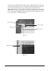
Caliper Tool
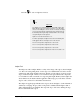
The Caliper Tool has a Caliper Window overlay on the image of the edge as shown in Figure
7 -4. The tool is strategically placed over the edges to be identified. The tool can be sized in
2-dimensions. The Search Length is the longer dimension of the caliper tool and crosses the
edge to define the length of the area to be searched for the gray transitions. It is important
not to include more than one transition or edge along this length. The Projection Length is the
shorter dimension, the distance that the application will average grey-scale values down the
edge in order to reduce noise and enhance the transition.
The calipers are applied perpendicular to the edges as shown in Figure 7 -5. The information
obtained by “averaging” the gray values of the pixels is calculated and the light-to-dark or
dark-to-light transitions are identified. The steeper the slope of the curve defining the edge,
the more well-defined the edge is.
TIP
Light Level
The Light Level controls brightness of the LED or fiber optic
lights directly. The vision system can have one or two light
sources. For finding the corner of a die on a board, one light
source may be better at casting the proper shadow onto the
board and producing the high contrast which is most easily
recognized by the Vision System.
Light Level can be varied from 0 - 15.
For fiber optic lights, the light levels are incremented by two
and toggle between each light source. This means:
Level 0 corresponds to Light Source 1 at Level 0.
Level 1 corresponds to Light Source 2 at Level 0.
Level 2 corresponds to Light Source 1 at Level 2.
Level 3 corresponds to Light Source 2 at Level 2, and so on.