
LLC Computer Hardware User Manual


3300565 User’s Manual I/O Port Pin Assignment
6
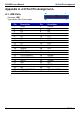
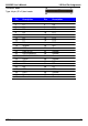
A.4 < CRT Port >
Connector: CRT
Type: 15-pin D-sub female connector on panel
1
11
2 12
3
13
4
14
5
15
10
Description Pin Description Pin Description
1 RED 6 Ground 11 N/C
2 GREEN 7 Ground 12 5VCDA
3 BLUE 8 Ground 13 HSYNC
4 N/C 9 LVGA5V 14 VSYNC
5 Ground 10 Ground 15 5VCLK
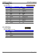
A.5 <Serial ATA Port>
Connector: CN_SATA1/2
Type: 7-pin wafer connector
1 7
1 2 3 4 5 6 7
GND RSATA_TXP1 RSATA_TXN1 GND RSATA_RXN1 RSATA_RXP1 GND
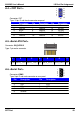
A.6 <Serial Port>
1
2
6
3
7
Connector: COM1
4
8
5
9
Type: 9-pin D-sub male connector on rear panel
Pin Description Pin Description
1 DCD 6 DSR
2 SIN 7 RTS
3 SO 8 CTS
4 DTR 9 RI
5 Ground
CRT Port 49